
|
|
|
#1
 01-25-2012, 02:23 AM
|
|||||
|
|||||
|
My ATI Powermodule 8x54watt mod…
I bought this beautiful beast of a fixture from viper901 mid-December (thanks Dude). He moved his tank and this unit would no longer fit over the new location. Don’t feel sorry for him though…he bought himself some Radions!!! This fixture is awesome, both in build, and PAR 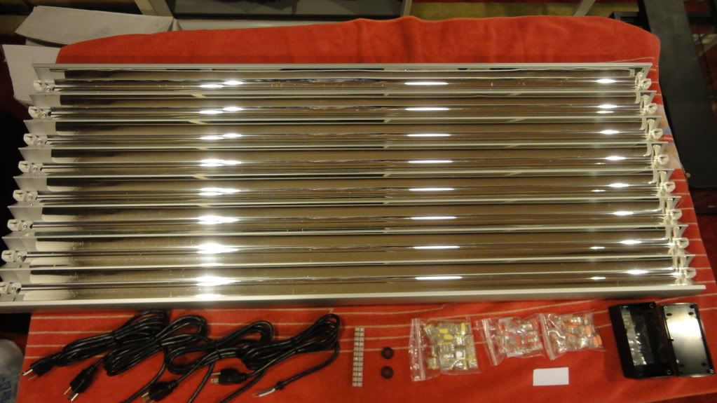 Sorry it's blurry 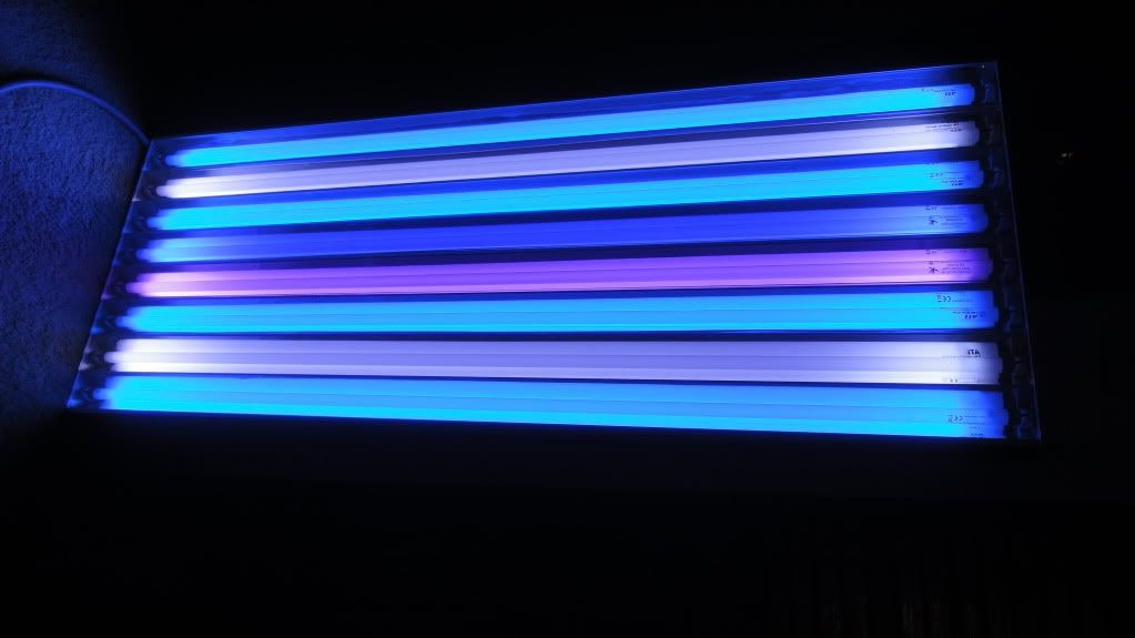 The only thing I don’t like about this ATI is the lack of bulb control. I was aware of the 2-bulb and 6-bulb connectivity before I bought it, but knew I could do something as the unit has 4 x 2-bulb ballasts. Also, because the unit is more than a year old, and I am not the original owner, the warranty is Kaput. I am pretty sure what I have done will work for any of these fixtures with 6 bulbs or more. WARNING: The following contains information that could lead to catastrophic light failure, serious personal injury and even death. Performing these wiring modifications without proper knowledge/care is not advised. The author takes no responsibility for any blah, blah, blah, (insert appropriate legal jargon here). NEVER WORK ON YOUR LIGHTS WHILE THEY ARE PLUGGED IN !!! I started my butchery by removing the end caps to have a look at how it was wired. I then opened the little junction/clamshell box and again inspected the wiring. 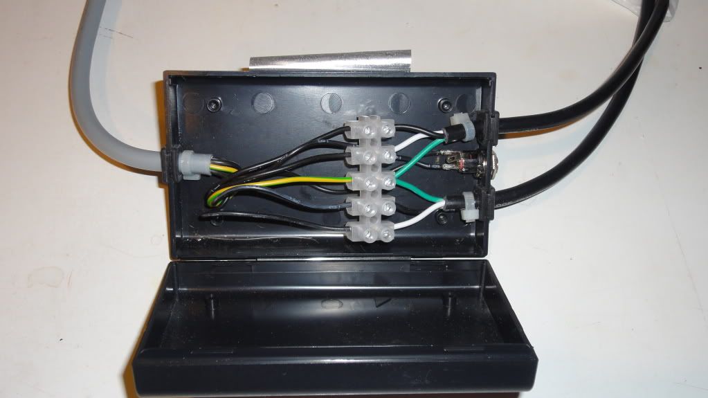 Next, I searched all over the web for what I would need. It took some time, as finding the supplies in reasonable quantities is not so easy (at least that’s what I found). I bought what I feel is almost exactly the same kind of wire, connectors and terminal-strip that ATI uses. I also grabbed a plastic project box that will do the job. The parts list is further down. On a side note: one could get by with adding a 5-wire to the existing setup, but I only wanted one wire from the junction box to the fixture. How you wire your ballasts is subjective. OK, lets get on with it. Tools needed: #1 Phillips screwdriver #20 Torx driver 7mm wrench Needle nose pliers Wire cutters 5/16, 3/8 and 9/16 drill bits Dremel with metal bit or Small flat and round files From the factory on the 8-bulb unit I have, bulbs 3 and 6 are on their own ballast for sunrise-sunset. My modification takes this fixture to a 4-pair unit; up to 4 timers may be used to gently bring the lighting up and down. This will be handy for acclimating critters and so on too. I also rearranged the bulb/ballast relationship. Maybe down the road I’ll even change the ballasts to dimmable models. As stated above, the factory wired bulbs 3 and 6 together. They also wired 4 and 5 together. This is good. They wired 1-2 and 7-8 together. This makes perfect sense for production, but had to change. My bulbs are now paired as follows: 1-8 2-7 3-6 4-5 This was the easiest bulb/ballast configuration to rewire, as I only had to exchange the wiring between 2 bulbs: The end caps for bulb 2 were rewired from bulb 8, and the end caps for bulb 8 were rewired from bulb 2. Now the ballast in position 1-2 runs bulbs 1 and 8, and the ballast in position 7-8 runs bulbs 2 and 7. Extra 18Ga wire is needed for this. You must rewire both ends of each bulb you change. If this is not clear, have someone help you with your project! First is the ATI wiring layout: Upon carefully peeling back one of the labels on the junction box, I found it’s nearly empty (Image above). All it contains is the visible outside wires and a 5-port terminal block. I ruined the 12V socket trying to remove it and bought another. It’s 2.1mm x 5mm (linked below). The 6 wires from the 2 x 120v supply cords connect to this block, with their grounds connected together in the center (thus making 5 pass-through connections). The 12v DC socket is wired directly to the fixture: more on that further on. The gray cord from the fixture is comprised of 7 wires. One wire is the yellow/green (y/g) ground, and the other six are black, numbered 1 through 6. The y/g connects to the center of the terminal block, wires 1 through 4 are each connected to their necessary 120v hot and neutral wires, and the last pair goes directly to the 12v DC socket. Inside the fixture, the DC wires are connected to the fans via push-in connectors and more wire, creating wire extensions. The 2-bulb ballast is wired directly. ATI then used a number of push-in connectors to further attach the other 3 ballasts to the gray supply cord. Next is the mod I don’t see the need to go into great detail here. The only thing I recommend is you cinch zip ties on the cables inside the box and fixture to prevent pullout. Ya, I said pullout. Junction box; 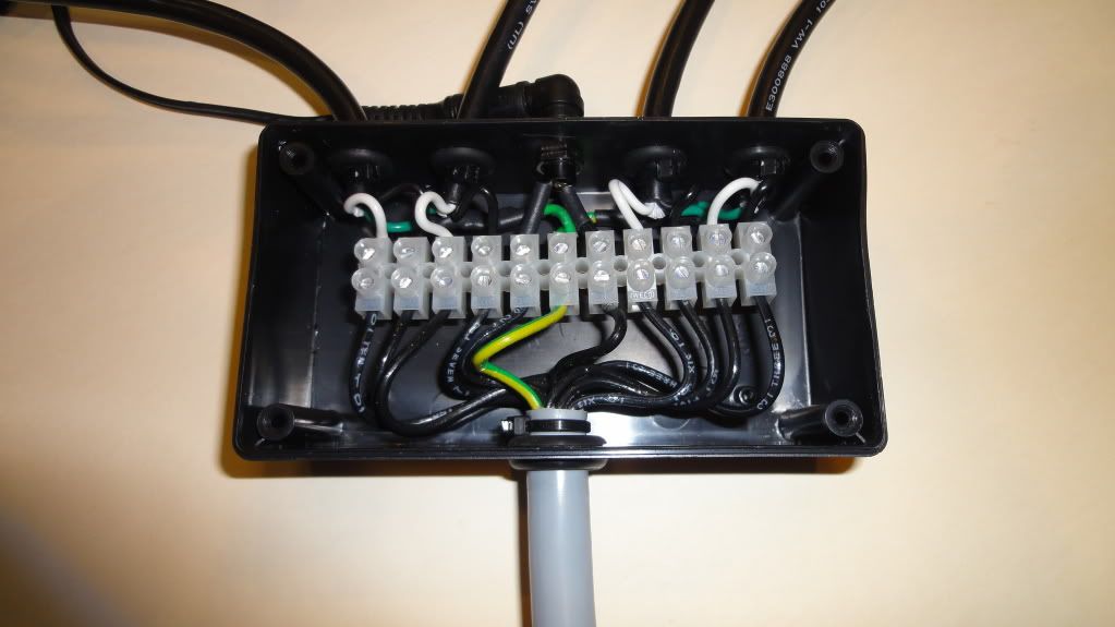 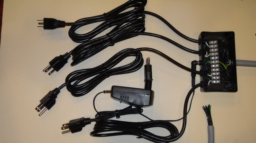 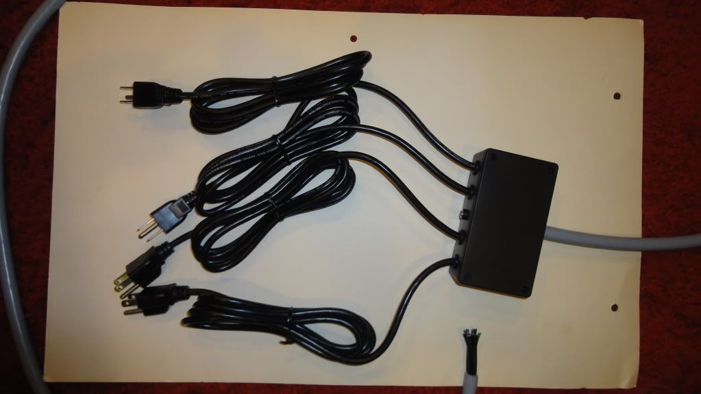 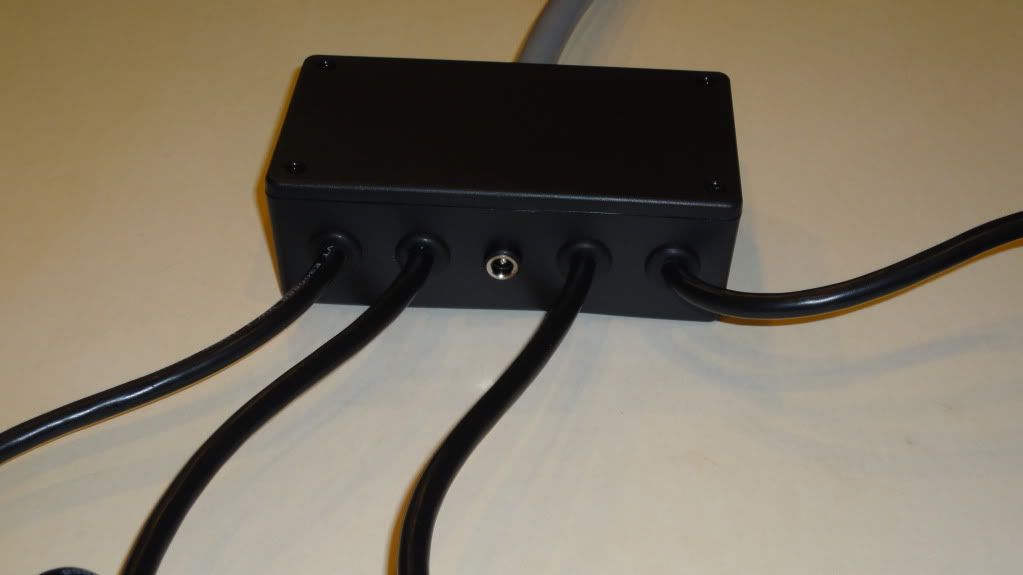 I drilled 5 holes on one end of the junction box; four 3/8” grommet holes for the 120v supply cords, and one 5/16” hole for the DC socket. Then one 9/16” hole was drilled on the opposite end for the patch cord. Terminal Strip; To connect everything to the terminal strip; I wired all 4 120v supply grounds together and they mate up with the y/g ground; the wires numbered 3 through 10 go to their respective hot and neutral mates from the supplies; wires 1 and 2 are for the DC socket. These could be run direct, but I chose to connect them to the strip. Wire 11 is unused. Fixture; I modified the fixture’s original cutout for a larger grommet to accommodate the supply cord. 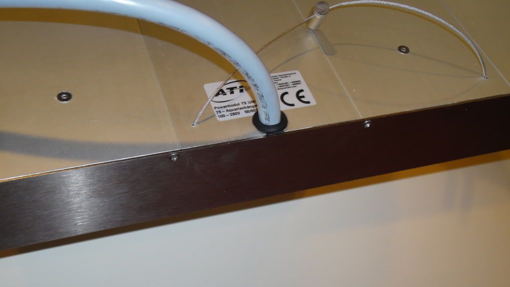 I patched the ring connector for the new y/g ground, but only because I didn’t have a new ring connector small enough. It is held in place by one of the center ballast screws. This is factory 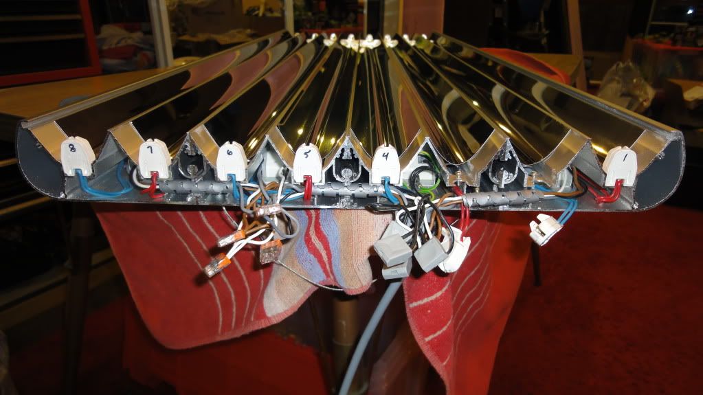 And this is how it looks after all the wiring is done. 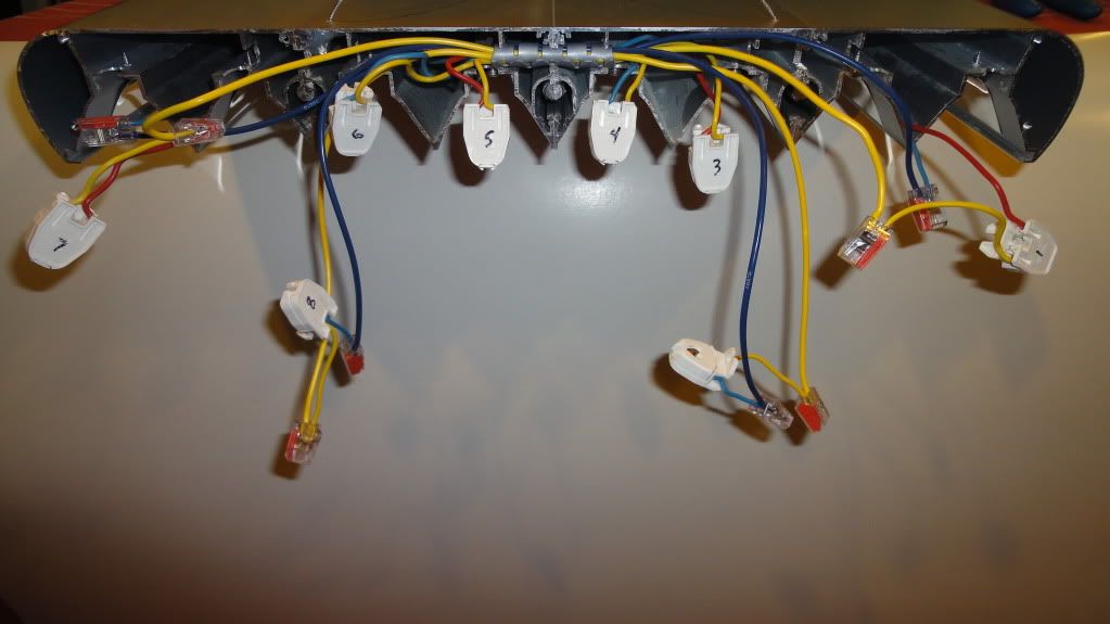 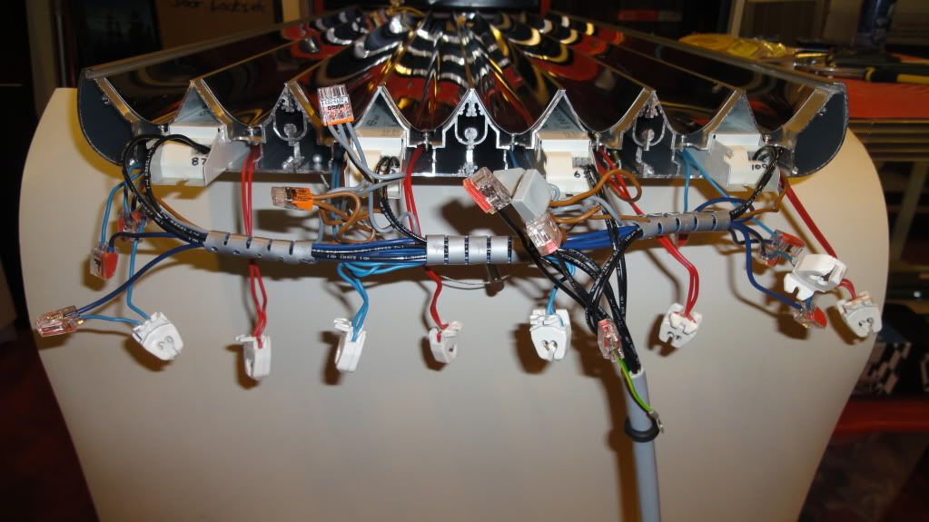 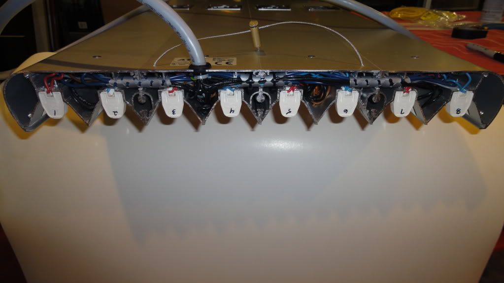 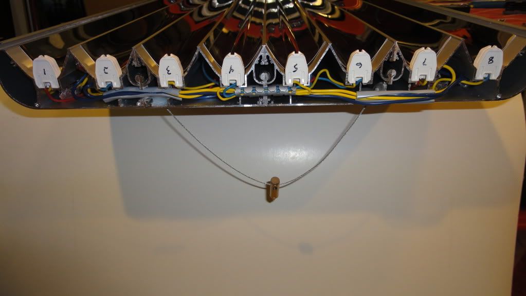 And lastly is the supply list: I had extra 18ga Yellow and Blue wire and grommets around the house. You will need both. If you use stranded wire, it must be soldered to work correctly with the push connectors. Wire http://www.alliedelec.com/search/productdetail.aspx?SKU=6500284 Power cables http://www.alliedelec.com/search/productdetail.aspx?SKU=5922237 Terminal strip http://www.alliedelec.com/search/productdetail.aspx?SKU=9240100 Junction/project box http://www.alliedelec.com/search/productdetail.aspx?SKU=8062263 DC Socket https://www.rpelectronics.com/31-134...ack-pkg-2.html Push-in wire connectors http://www.ebay.ca/itm/25-See-Splice-2-Connector-RED-Push-Wire-Nuts-22-12-/390298933530?pt=LH_DefaultDomain_0&hash=item5adfa1 191a Please, if you are not well versed in wiring, especially high-output type stuff, don’t do this on your own. You could kill yourself, or worse, lose lots of money destroying this nice fixture. Last edited by gregzz4; 01-25-2012 at 07:49 PM. 
|
|
#3
01-25-2012, 02:52 AM
|
|||||
|
|||||
|
look again?
|
|
#5
01-25-2012, 03:10 AM
|
|||||
|
|||||
|
Quote:
I hope my thread helps someone one day as I had no idea what the guts of my fixture looked like before I bought it. I'd like to see huge amounts of views
|
|
#7
01-25-2012, 04:11 AM
|
|||||
|
|||||
|
Quote:
I'm not much of a writer, but if you like this thread, a rating would be appreciated
|
|
#9
01-25-2012, 04:22 AM
|
|||||
|
|||||
|
Thanks Ma Na Ma Na
I forgot to link a couple pics of the whole fixture. Give me a minute to get them up.
|


 Linear Mode

