Canreef Aquatics Bulletin Board  

Go Back   Canreef Aquatics Bulletin Board > General > DIY

Reply
 
Thread Tools Display Modes
  #1  
Old 04-28-2013, 03:12 AM
byee byee is offline
Member
 
Join Date: Mar 2009
Location: Coquitlam
Posts: 291
byee is on a distinguished road
Default

Quote:
Originally Posted by daplatapus View Post
Well, I had a good talk with an electrician that I use and he helped me wade through some of the dilemma's I've had. He's not a electronics guy, just a sparky who does house and commercial wiring but his code book pointed us in the direction I think I needed. Turns out a 18AWG wire all by itself in the open air can carry 10A but it's de-rated once it's bundled with a bunch of others. The ratio of decreased carrying capacity depends on how many wires it's run with. But according to our math 18AWG should be fine for what I'm doing. And as it turns out he had a roll of 18/21 sitting in his shop he gave me for $2/ft. It is fire alarm wiring.


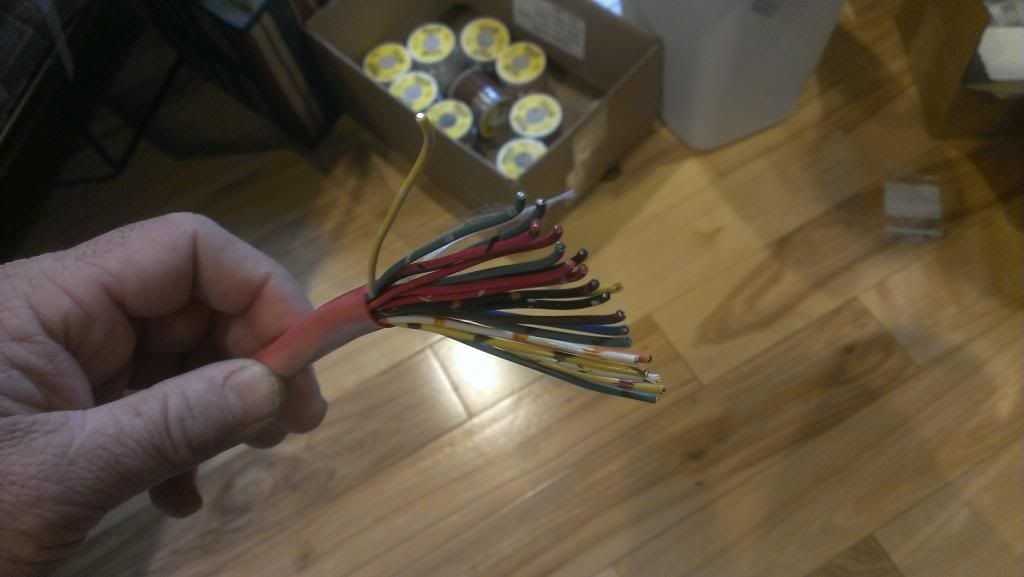
And I also got some other goodies in the mail yesterday. Now all I have to do is figure out how it works

daplatapus,

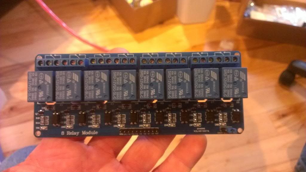
Send me a close up digital picture of the header pins for input.

I just received mine last week but the 4 relay version. The relay modules are opto-iso which will require the pin to be tied to gnd to latch. From what I've found out over the last week, the opto-iso is not compatible with the Jarduino.

Simply put........the relay board latches on GND but eventually becomes inconsistent also latching on 3.3 to 5VDC.
Reply With Quote
  #2  
Old 04-28-2013, 03:16 AM
daplatapus's Avatar
daplatapus daplatapus is offline
Member
 
Join Date: Apr 2012
Location: Port Alberni, B.C.
Posts: 1,315
daplatapus is on a distinguished road
Default

Ya, I was actually just reading something about that on the jarduino thread on UKreefs. But I admit I'm not sure what all that means or what to look for for a proper relay board
Give me a sec and I'll post the pic.
Reply With Quote
  #3  
Old 04-28-2013, 03:23 AM
daplatapus's Avatar
daplatapus daplatapus is offline
Member
 
Join Date: Apr 2012
Location: Port Alberni, B.C.
Posts: 1,315
daplatapus is on a distinguished road
Default

One of the input pins:


One of the actual relay modules:


and one of the jumper pins on the far right of the board:
Reply With Quote
  #4  
Old 04-28-2013, 03:25 AM
daplatapus's Avatar
daplatapus daplatapus is offline
Member
 
Join Date: Apr 2012
Location: Port Alberni, B.C.
Posts: 1,315
daplatapus is on a distinguished road
Default

If anyone is interested, I'll probably be making a custom order for the 4-LDD pcb boards with the pull down resistor jumper that rrasco made on the RC thread. PM me if you interested in any of the boards...
Reply With Quote
  #5  
Old 04-28-2013, 05:05 AM
ScubaSteve ScubaSteve is offline
Member
 
Join Date: Nov 2009
Location: Vancouver
Posts: 1,591
ScubaSteve is on a distinguished road
Default

Quote:
Originally Posted by daplatapus View Post
If anyone is interested, I'll probably be making a custom order for the 4-LDD pcb boards with the pull down resistor jumper that rrasco made on the RC thread. PM me if you interested in any of the boards...
Sign me up for 4! I'm glad to see he added the pull-down after I suggested he do it... Unfortunately he did it after I build this tank

New LEDs for the main tank coming it the summer! Whoooo!
Reply With Quote
Reply


Posting Rules
You may not post new threads
You may not post replies
You may not post attachments
You may not edit your posts

BB code is On
Smilies are On
[IMG] code is On
HTML code is Off
Forum Jump


All times are GMT. The time now is 11:22 PM.


Powered by vBulletin® Version 3.7.3
Copyright ©2000 - 2025, Jelsoft Enterprises Ltd.