 |
|
#111
|
|||||
|
|||||
|
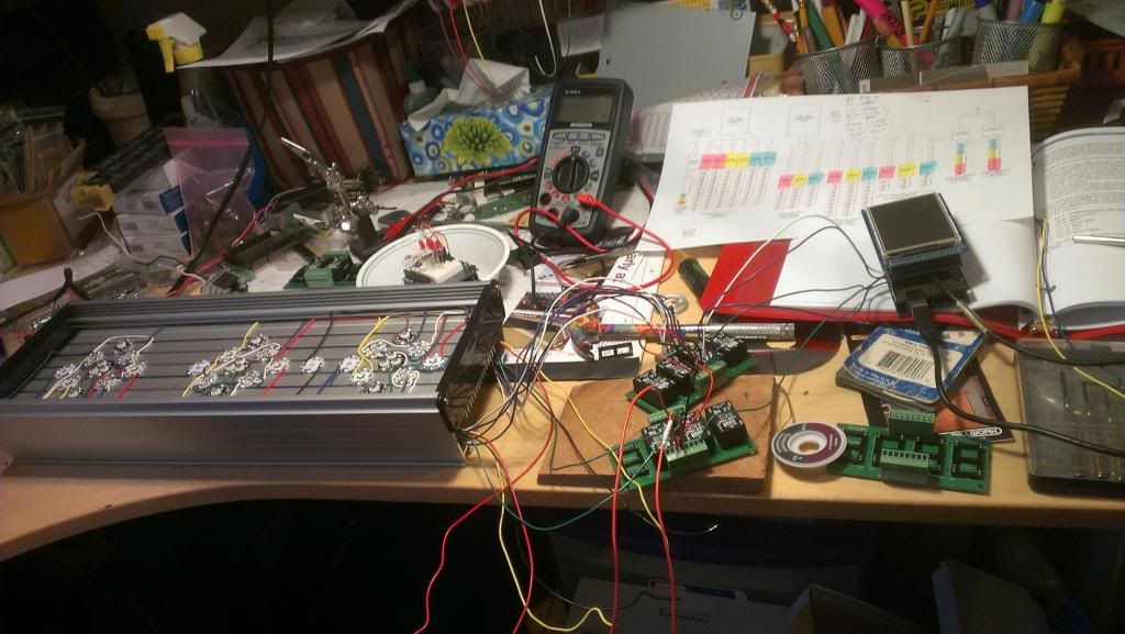
Well, something woke me up early this morning so I got up and tried to figure this out. I have one heatsink ready (somewhat, still waiting on some connectors) but I strill didn't know if everything worked in conjunction with the Jarduino. So I spent some time re-reading the original RC thread and temporarily hooked up what I have. Here's the pre-powered up pic in case I blew something up
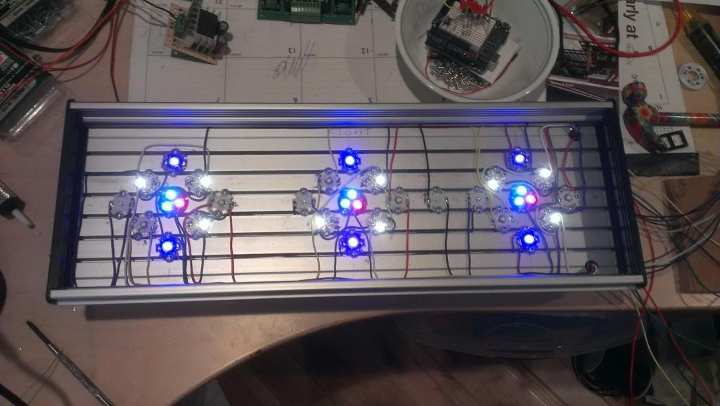
  Crossed my fingers and powered everything up..... YAAAAAA!!! It works! It's alive !!!!! Switched the screen over to test LED mode and worked the sliders and everything works awesome! 0% dimming and everything. So I took a pic at step 1 of the sliders so the crappy phone could take a pic of it. I only have the XT-E NW's, RB's, TV's and the OCW channels hooked up, but you get the idea.  EDIT: Actually now that I look at the pic I must have turned the RB's to 0 as they're not on in the pic, but they do work |
|
#113
|
|||||
|
|||||
|
LOL, HAHA. Busted! I was too lazy to get mine so I used my wife's to punch out the unused pins on the 24 pin IC socket adapters.
|
|
#114
|
||||
|
||||
|
LOL... I completely missed that. I had to go back and look at the picís, I thought I missed a post with a tank shot or something. It IS a sweet looking hammer though.
__________________
All spelling errors are considered intellectual property of its owner, and are not to be tampered with |
|
#115
|
|||||
|
|||||
|
So, I'm re-thinking my connector issue. Just my LED's are going to take 16 wires. The heat sensor takes 3 and the PWM fans take 3 for a total 22. Been thinking of going with a DB25 connector affixed right to the heatsink and a breadboard mount DB25 by the arduino with a disconnect-able cable between them for each LED fixture. Any thoughts?
|
|
#116
|
||||
|
||||
|
I've been jumping between sites trying to keep up with everyone building the Jarduino.
Not sure if this was the forum but someone had purchased multichannel LED drivers from eBay. I'm looking for one of these multichannel LED drivers for my second Jarduino - development system. If someone has the link, please point me in the right direction. Thank you! |
|
#117
|
|||||
|
|||||
|
Hmmm, might have been Mike31154. Check his multichip build thread. http://www.canreef.com/vbulletin/showthread.php?t=82206
|
|
#118
|
||||
|
||||
|
I would just double check what the connector is rated for, but sounds like an option. Even the molex connectors from an ATX powersupply would work. (24 pin ATX power connector) My vote would go to an amphenol 97 series circular connector.... but they are pricey.
__________________
All spelling errors are considered intellectual property of its owner, and are not to be tampered with |
|
#119
|
|||||
|
|||||
|
Wow, you ain't kidding, $70 ea for 22 pin. And I'd need 12 for the connections and cords. Don't think so, lol. I'll keep looking though, I like the build of them.
|
|
#120
|
||||
|
||||
|
$70 would be on the high side, all depends where you order. There are other manufacturers that make simillar connectors that are less expensive, just can't think of the name at the moment. ( I've mainly only used the amphenols )
__________________
All spelling errors are considered intellectual property of its owner, and are not to be tampered with |