![]() |
|
#1
|
|||||
|
|||||
![]() The stand should have been delivered to Red Coral today (woohoo!). The sump needs to go in before the stand is placed on top of it, so I made more formalized drawings before 'taking the plunge' and ordering tomorrow. If anyone has any input in to this design, please, please, PLEASE let me know.
I sat down with the computer and worked out proper 'to scale' drawings of the sump. I've drawn two versions, version 1 will only fit a Deltec SC 2060 skimmer, and version 2 will fit a Deltec SC 2560. Based on manufacturer specs, the 2560 seems like it's a bit of overkill for my size of aquarium, but I like it for 3 reasons: 1. In V2 the water change chamber is smaller (approx 17% of display volume), so at any given moment I'll have less opportunity to change the water. If that is the case I want to have maximum nutrient export methods possible. I can still do larger, manual water changes, but the point of this tank is to build something that doesn't require me to get my hands wet (though I know I will cuz I love getting my hands wet), so I want to only use the water change chamber to do my water changes. 2. The SC2560 is the smallest size you can have the Deltec auto-cleaner for their skimmer. I won't get one right away, but I love the idea and I want one eventually. 3. Even if I get an SC 2060, I have extra space for a later upgrade (though for how expensive those things are, I will need to start playing the lottery if I'm thinking about 'upgrading'). The other thing I did on both versions that I need some input on to know if it's possible: In my first design I was afraid that water wouldn't flow through the entire sump, leaving dead spots in the water change chamber (on the right), so I added a central baffle that will force water to flow more in a true 'U' shape. At first I had it so that the baffle had a cut out so that water flowed over the cut out section, but then I realized that I would be creating a dam that would prevent me from being able to completely drain the water change chamber with one pump. I hope that instead I can have that baffle flipped upside down. I drew it on the plans so I hope you see what I mean. I made the bubble trap section exactly 6 inches wide (total width), which is what I've heard is the standard width for a bubble trap. I don't know how thick the glass needs to be so I really just drew it in as a place holder. I want the water height in the sump to be 17 inches when the sump is running, so I made the middle baffle of the bubble trap be 17" high, I might need it to be 16.5" high, not sure yet. I also left a full 2 inches between the final bubble trap baffle and the baffle that separates the water change chamber and the skimmer/refugium chamber. If I can get away with less that 2 inches let me know as that would give me more space between the drains from the tank and the skimmer. The other thing I added was a 3.5 inch wide trough between the entrance to the refugium and the exit from the water change chamber. It's only 7 inches high because I don't want to completely isolate the refugium, but it will keep the most forceful stream of water from directly hitting the regium. If anyone thinks this trough needs to be wider let me know, but I would like to keep it as narrow as humanly possible so that the refugium can be as large as possible (this is part of my desire to have as much nutrient export as possible so that a smaller water change chamber isn't such a big deal). I have also looked up the various reactors I think I'd want. The biggest reactor (the ones that could hold zeovit or biopellets) should be able to sit on the floor to the left of the sump, since I'm leaving 12 inches of space between the sump and one side of the cabinet, and the return pump is only about 12 inches long. At the moment I think I'd at most want two other reactors (3 total), and since I'd be using them for things like activated carbon and a phosphate absorber, they can be the large size TLF reactos that can hang off the side of the sump in the refugium chamber. At best, I need no reactors in the water change chamber. At worst, I need one reactor in the water change chamber, but I would put its pump and output on the other side of the central baffle so that even when I drained the water change chamber, it would remain on, full of water, and never be affected by the water change. This will also leave me the option to add a calcium reactor one day if I wanted (I think) The one thing I didn't account for was how thick the the baffle between the two sides of the water chamber are. If it needs to be half inch thick, then each half of the water change chamber will be either 14"x23" (sump 1) or 14"X21" (sump 2). As before, the green line shows the flow of water when the gate valves are open, the red line shows the flow of water when the gate valves are closed. Sump option 1 (skimmmer Deltec SC 2060) ![]() 
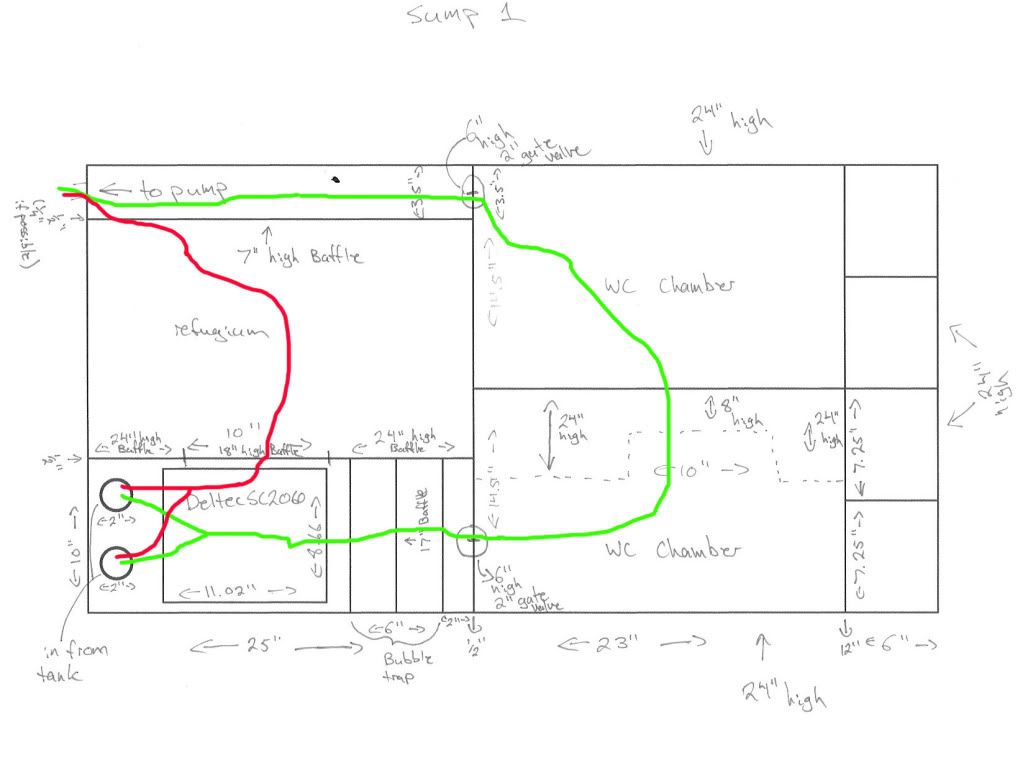
Sump Option 2 (skimmer Deltec SC 2560) ![]() 
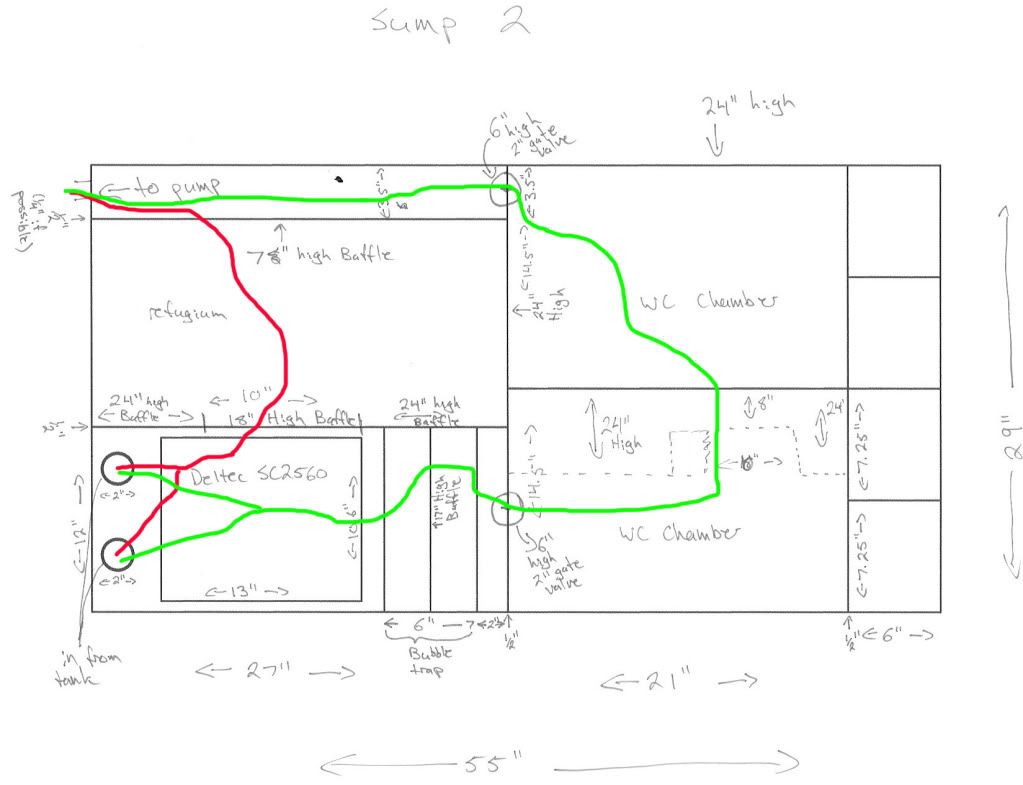
Last edited by asylumdown; 05-27-2011 at 05:03 AM. |
#2
|
|||||
|
|||||
![]() from what i can make out of this design, you may have some major micro bubble issues with it. I am just guessing, but it looks like the refug over flows into the return chamber, if the water level in the return chamber fall below the 7 inches you will have some turbulence right in front off you return pump which is not a good thing. also the bubble trap after the skimmer is not needed from what i can tell, bubble traps are usually used just before the return chamber to control the amount of bubbles getting into the pump, you should only have a baffle after the skimmer to control how high the water level should be in that chamber. hope that makes sense lol but i could also be reading your design wrong too
![]() |
#3
|
|||||
|
|||||
![]() The water in the return chamber should (hopefully) never fall below 7 inches. In order to be able to do the largest water changes possible, I had to increase the depth of the water in the sump to 17 inches. It will mean the skimmer needs to sit on about an 8 inch stand, but I have a custom height aquarium stand and the Deltec's are 23.62 inches tall (it's why I chose them), so I still have plenty of clearance between the bottom of the aquarium and the top of the skimmer. That will mean that the baffle between the fuge and the return channel will always be under about 10 inches of water. I only created that baffle so that water entering the fuge/return channel from the water change chamber wouldn't be blasting at it's highest velocity over sand & algae, and to hold the sand up from falling in to the return line. If that's the case, do I even need a bubble trap?
If I had no bubble trap, I have 2 options: 1.Put an 18.5 inch baffle right after the skimmer so that the water level in the skimmer/input chamber would be a constant 18.5 inches. I still have plenty of clearance between the top of the skimmer and the bottom of the tank if I make the stand the skimmer sits on 9.5 inches high. Then the water would pour into another chamber created by the space between the 18.5 inch baffle and the centre baffle. During normal operation, the water height in the rest of the sump would be 17 inches, but when I isolate the water change chamber to do a water would, the water in the chamber after the skimmer would rise until it poured in to the fuge. This design would have some water tumbling during normal operation, but it would be tumbling several feet (if the water path was a straight line) before the return pump. 2. Not have any height setting baffles at all. The water height in the entire skimmer would be 17 inches, and the entire sump level would fluctuate with evaporation. When I close the gate valve between the sump chamber and the water change chamber, the water will rise an inch to an inch and a half before it pours over in to the refugium chamber. There's going to be an auto-top off system, so this might be feasible. Any thoughts? Also, would making that channel from the water change chamber to the return pump 4 inches wide be enough for a 1 inch return line?, that would leave 1 inch on either side and a 2 inch hole. |
#4
|
|||||
|
|||||
![]() ok i did a crude markup of what i can tell is happen, but there are a few area i am not sure what you had in mind
![]() ![]() if you can tell me if this is close to what you had in mind or if i am missing something in this. ok here are the areas that are confusing me 1)where the bubble trap after the skimmer does not seem to go any where 2)the water change chambers, what are they there for and why two? 3)it sound like you want to put gates values under water, i am not sure but i bet that may not be the best option as there is metal screws on the one that i have seem 4)what are you putting in the refug? a drop of 18 inches to even 10 inches for the water is going to make a lot of bubbles, that very close to where you return is |
#5
|
|||||
|
|||||
![]() Holy crap that's incredible.
The one thing that's missing from that render is the opening in the central baffle that cuts the water change chambers in two. I have no way of drawing in 3-D so I just marked it up in pen on my drawings. Here's the theory: When the sump is running, the two gate valves in to the water change chamber are open, so that water enters the sump in the skimmer chamber, goes past the bubble trap, through gate valve 1 in to the front section of the water change chamber, through the opening in the baffle that cuts the water change chamber in two, then through the back gate valve in to the channel in the refugium. Essentially, during normal operation, the full size of the sump (except for the 4 dosing containers) will have tank water flowing through it. The only time water will pour from the skimmer chamber in to the refugium is when I'm doing a water change. Water changes will happen by first closing the gate valve between the skimmer chamber and the water change chamber. Water will then fill up the skimmer chamber and pour over in to the refugium. Once everything has levelled out again, I'll close the second gate valve between the return area and the water change chamber. This will totally isolate half of my sump and divert the water temporarily directly in to the refugium. Now, I will have the auto-top off feed line and sensor inside the water change chamber. There will also be a pump with a line directly out to the sewer inside the water change chamber. Once the water change chamber (or two chambers I guess) are isolated, I will kill power to my auto-top off system and turn on the drain pump on that side of the sump. Once the water change chamber is drained, I'll turn power to the auto-top off system back on and let it fill the water change chamber up with fresh R/O water (the reservoir is in the basement beneath the tank). Then I add and mix salt, open the gate valves, and return the water change chamber to the circuit of the sump. It forces the water to completely change direction in the sump. Originally I didn't have a central baffle that divided the water change chamber in two, but I wanted to forces it to flow through the whole sump and not end up with dead spots in the corners of the water change chamber. I *hope* that it's possible to make the opening between the two halves of the water change chamber be at the bottom of the sump, as opposed to a cut out at the top, as this will allow me to completely drain the WC chamber with just one pump. The logic behind this design: I have no fish room, the only remote equipment I can have is the R/O reservoir. Everything else needs to fit under the tank. It's getting built in to the house, so I wanted to be able to automate water changes as much as possible, but not sacrifice sump volume by taking up floor space with a separate water mixing container. I also need to be able to do a significant enough of a water change to make it worth the whole endeavour, hence the height of the sump, and the 17" water depth within the sump while it's running. Is what I'm thinking about even possible? |
#6
|
|||||
|
|||||
![]() looking at that in 3-D, it's making me re-consider whether or not the gate valves I have in mind are possible. I don't think that a 2 inch gate valve exists that has a handle 16 inches above the actual valve.
hmmmm. |
#7
|
|||||
|
|||||
![]() Oh man thanks, that's awesome. Yah, I basically didn't want to sacrifice any system volume or sump size to have a second salt water mixing container/storage under the cabinet. I figure if I can build it so that I don't need to hand siphon out water, and then hand ball in mixed salt water from a garbage can, that's optimal. Then if I can keep the volume I would otherwise use for the mixing and storing of water change water as part of my system, even better.
|
#8
|
|||||
|
|||||
![]() ok i think i know where you are going with this
![]() |