
|
|
|
|
|
#1
 05-07-2010, 06:18 AM
|
|||||
|
|||||
|
It's been a long time in the making but I figured I'd start a build thread seeing as my tank is almost ready to see some salt water. I puchased the tank second hand in Calgary over Christmas and have been slowly getting it ready to house the remains of my once great SPS reef that I previously had in a 90 gallon tank. I lost about 90% of my acros when I moved the tank in Decemeber so the new tank is going to look pretty empty since all I have left is about 1 dozen small frags that I managed to save.
Here's a shot of the 1st round of die off after I moved. In total, I lost more acros than you could fit into two 5 gallon pails. 3 of the colonies I lost were over 10" - 18" in size. Life lesson: never move a reef tank when its -25 C. 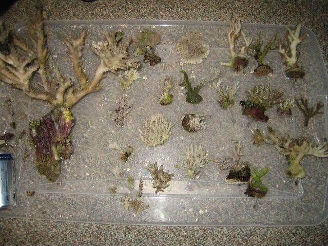 When I bought the setup, the tank came with a 2" steel tube stand, a psuedo finished wooden skirt for the stand, and a 77 gallon sump that was in really rough shape. I had to finish renovating my basmement prior to starting on the tank build so it took much longer than planned to start working on the tank itstelf. Plus work was always getting in the way since it takes me out of town for 1-2 weeks at a time. The first stage was to prep the floor for where the aquarium was going to go. I decided to remove the carpet and tile the floor to give myself a good solid foundation for the tank as well as waterproof the floor directly under and adjacent to where the tank would go. Dry fitting the tile 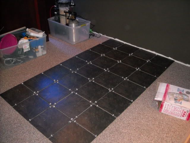 Removing the carpet 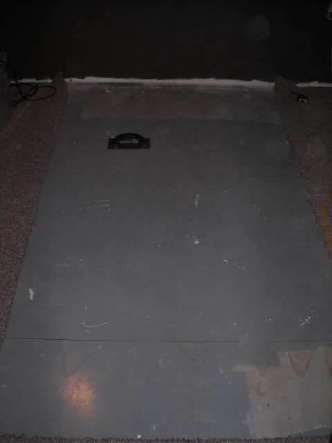 Installing 1/4" cement board 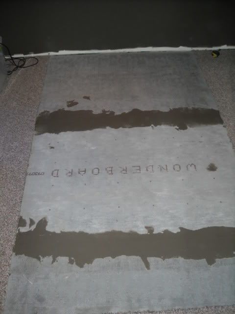 Mortaring the tile to the cement board 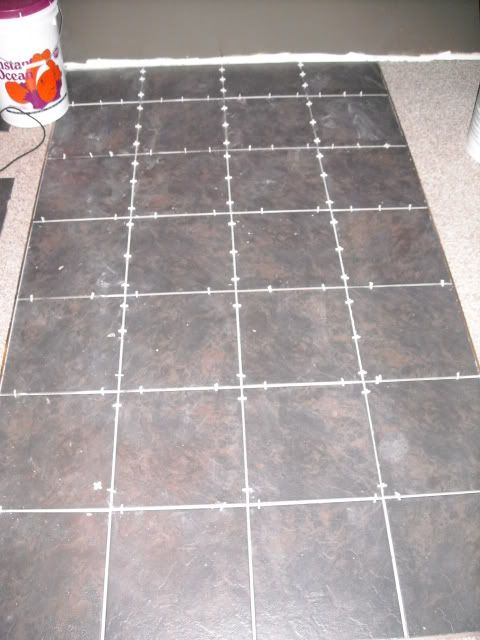 After grouting the tile 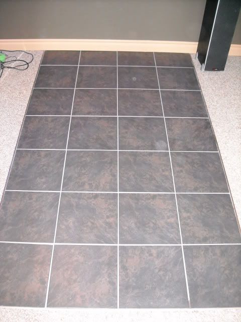 The tile actually looks much darker in reality but I kept getting a wicked reflection from the flash in every picture I took of it.
__________________
Do or do not....there is no try. 
|
|
#2
05-07-2010, 06:25 AM
|
|||||
|
|||||
|
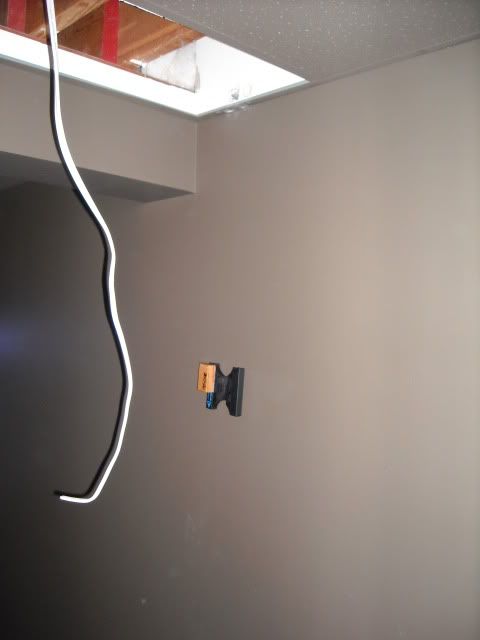
After I got the floor tiled, the next step was to bring in some electricity to power the tank. I didn't want to have extension cords hanging out either side of the stand so I decided to run 2 seperate 15 amp circuits to the wall directly behind the stand. Running the wires above the supsended ceiling was the easy part. Getting them from above the ceiling to the holes that I had cut near the floor wasn't quite so easy. After several "thinking" beers, I had an epiphany.
 However it seems that my idea to use a glass cleaning magnet to string a rope behind the drywall was only good in theory. The magnet with the rope attached on the inside of the drywall kept getting snagged on the insulation behind the vapour barrier and would get hung up. 3 and a 1/2 hours later and several more "thinking beers", Success! 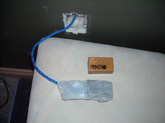 I really wasn't looking forward to doing the whole process again for the 2nd outlet however it only took about 10 seconds. The magnet didn't get hung up even once on the way down so that was most spectacular. After installing the outlets, the next step was to get my stand painted and sealed to create a moisture barrier. 3/8" Plyboard attached to form the bottom of the stand 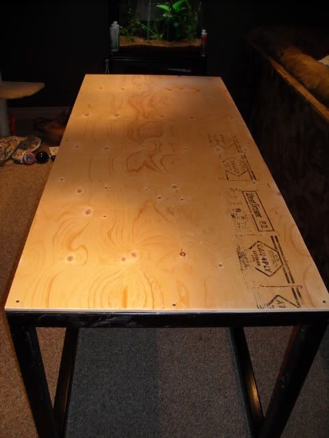 Stand getting primed and the bottom painted with oil based paint 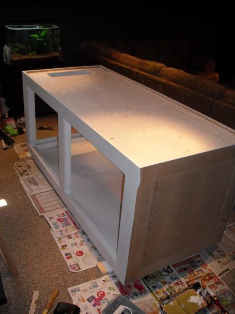 Exterior getting painted and I ran a bead of silicone where the 3/8" bottom plyboard meets the 2" steel stand. That way, if the worst should happen and I ever do get a leak, the stand itself should hold about 10-15 gallons of water before it overflows onto my basement floor. 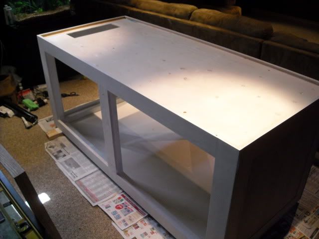 I still have to install the doors and finish the stand but that will be done after all the livestock has been transferred over from the 90 gallon tank. Once the stand was all painted up, myself and 2 friends lugged the heavy beast from the floor and got it centered and levelled on my tile. 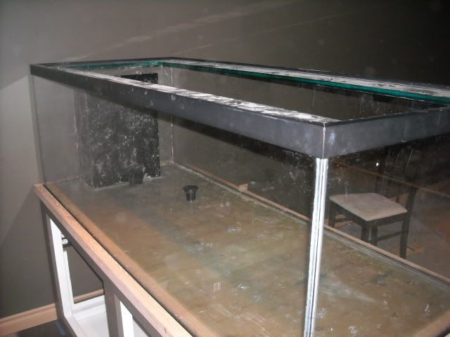 Once the tank was on the stand and I recovered about 25% of the floor in my basement, I started working on making the sump I received functional and reliable. I had to remove several acrylic baffles that were secured with what I can only assume was an entire tube of silicone for 2 baffles. Then I removed all of the inside beads of silicone as I was going to re-do these once I installed my own glass baffles. Sadly, when I was removing several pieces of 3/8" acrylic that the previous owner had siliconed over some holes that he was no longer using for bulkheads, a massive chip got taken out of the tank while I was removing the final piece of acrylic. 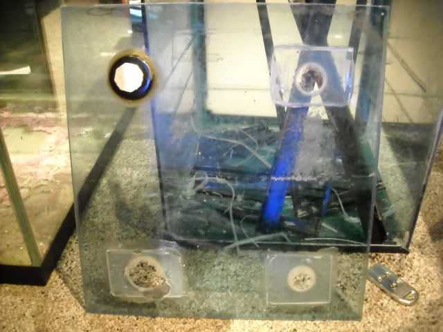 So obviously I had to remove the entire pane of glass and replace it. 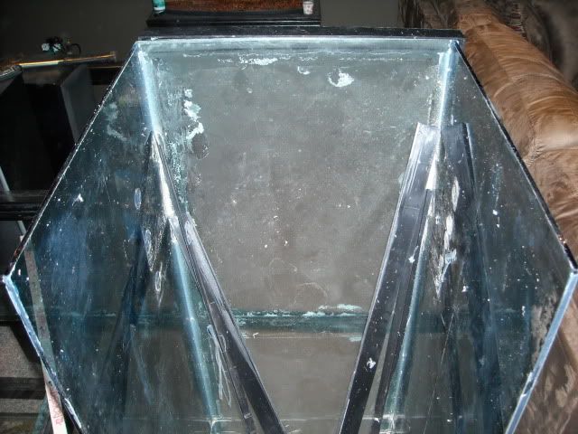 After siliconing in a new pane on the end of the tank, I re-siliconed the inside beads and started installing new baffles. 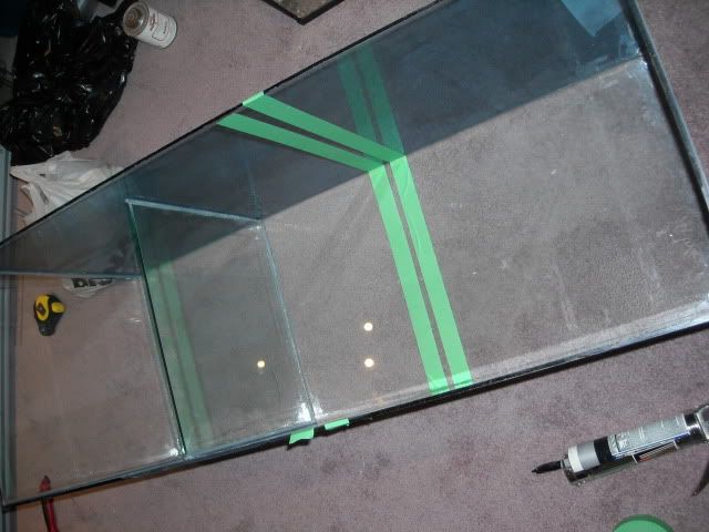 And here's a finished shot of the sump with the 3 different compartments. Skimmer will go on the far left along with a filter sock and a mag 9.5 to feed my manifold. The central compartment will contain 2 heaters and a mag 18 for the return pump. The right compartment will act as a refugium to store excess live rock and possibly some chaeto algae. 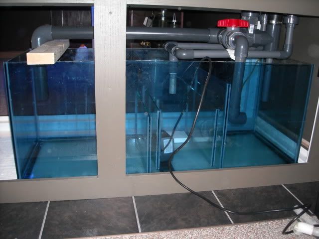
__________________
Do or do not....there is no try.
|
|
#3
05-07-2010, 06:29 AM
|
|||||
|
|||||
|
After I got the sump finished, I started working on the plumbing to connect the tank to the sump. After removing what seemed like another entire tube of silicone from inside of the overflow, I removed the existing 2" and two 1" bulkheads from the holes in the glass. I replaced these with new bulkheads since the previous ones had fittings glued and not threaded into them.
The way the return lines were setup, I decided to do a 2 in 1 style herbie overflow utilizing the 2" hole for both the main drain and emergency overflow. The other 1" holes in the overflow were used for the return line since they lined up perfectly with the bulkheads for the return outputs in the top of the overflow pointing into the tank. Here is the finished product 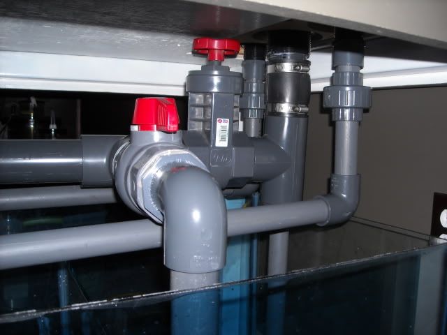 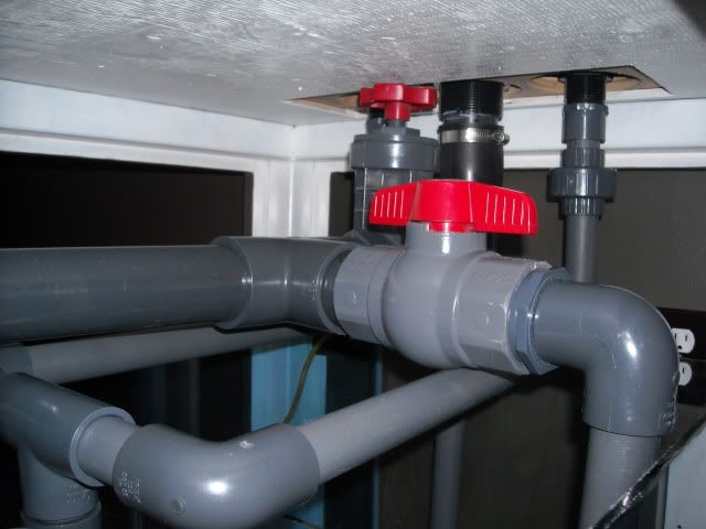 Here is the manifold I glued together. It will be fed by a mag 9.5 and the outlets will deliver water to my calcium reactor, UV sterilizer, phosban reactor, Vertex media reactor, and I left 1 outlet open incase I add any other new device that requires a feed of water in the future. 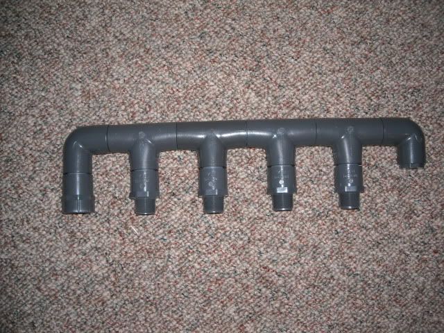 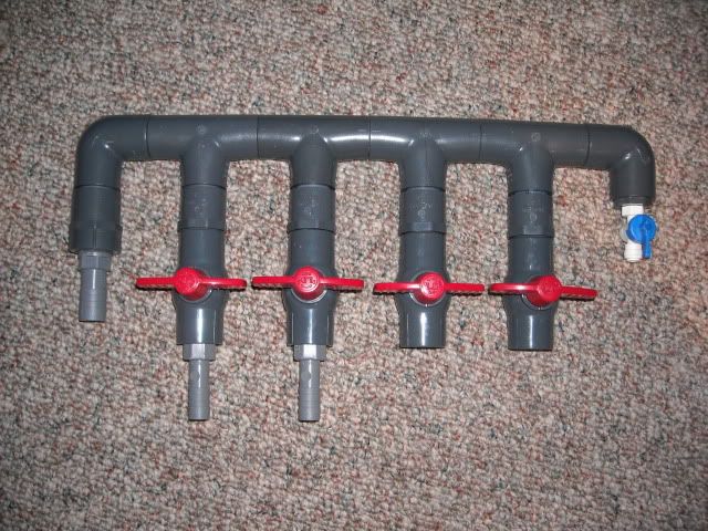 Here is a little schematic I drew up to explain how I plumbed the herbie overflow using only a single 2" pipe. 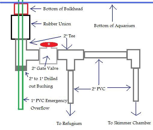 Basically, water drains down the bulkhead into a space between the inside diameter of the bulkhead (which will soon be getting a piece of 2" sched 40 PVC jammed in there to prevent my entire overflow from draining when the power goes out) and the outside diamter of the 1" pipe in the center of the bulkhead. From here, the water travels down to a T where it passes through a gate valve that serves to regulate the height of the water in my overflow. If I close this gate valve too much, the water level in my overflow fills up to the point where it starts flowing into the 1" emergency overflow pipe which sits approximately even with the top of my overflow. In the event the gate valve becomes clogged completely, the 1" emergency overflow will handle all of the flow from my return pump so there is no way the tank "should" be able to overflow. All I had to do was drill out a 2" to 1" Slip reducing bushing so that the 1" pipe could slide through. 2" to 1" reducing bushing right out of the box 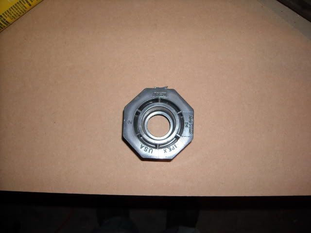 And after a little bit of dremel work. You can see that the central ring is now gone which allows a 1" pipe to pass all the way through the bushing instead of bottoming out half way in. 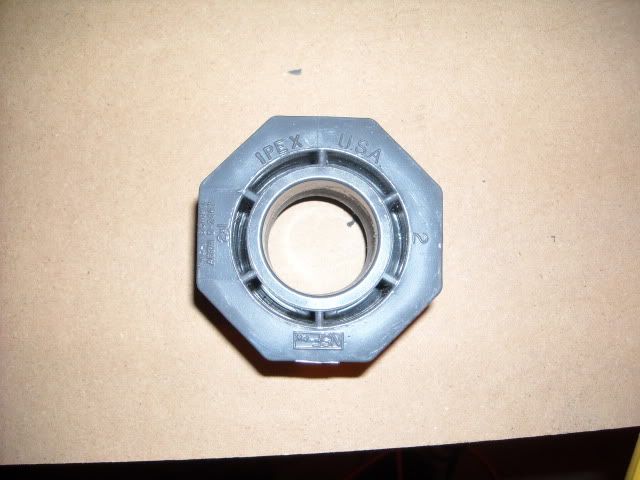 Then I slid the 1" pipe through the bushing and glued the bushing into the bottom of the 2" T on my drain assembly. The 1" pipe I did not glue in case I ever want to adjust the height of my emergency overflow. Even with the gate valve fully closed, I only get a slow drip out around the 1" pipe through the bushing. This doesn't matter though as it drips directly into the refugium anyways. 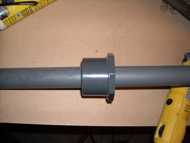
__________________
Do or do not....there is no try.
|
|
#4
05-07-2010, 06:34 AM
|
|||||
|
|||||
|
For whatever reason, the previous owner decided to keep the overflow comb for himself so I was left with nothing but some silicone residue on the top of the pieces of glass that formed the overflow. So I figured this would be a perfect time to test out my new table router.
First I cut the pieces of acrylic to size with an 80 tooth blade on my table saw. 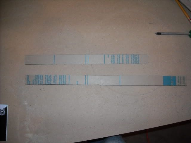 Since the max height my overflow comb could be was 1", I decided to go with 3/8" acrylic in order to make the comb a bit more rigid. After I cut the pieces of acrylic to size, I started cutting out the notches using my router table. The router table worked real good to cut the first few teeth but since the fence on the table would only go back 2 1/2", I could only cut 4 teeth. Since my overflow is 14" long, and I had 18 teeth to cut out in total, I had to come up with another idea. So I tried building a secondary fence and feeding the acrylic in perpendicular to the "proposed" feed direction. The result, an Epic Failure. 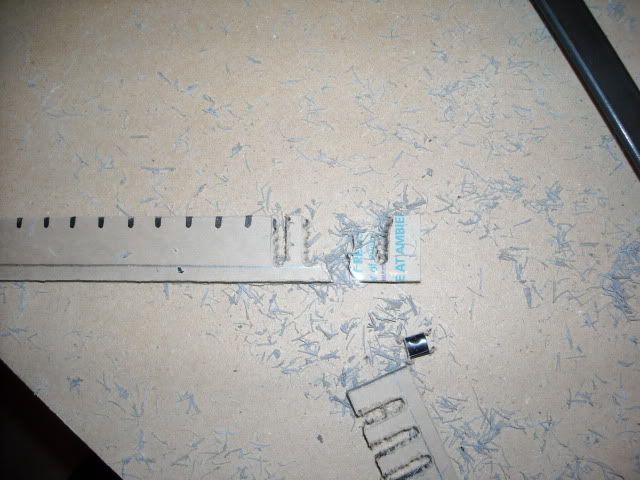 So after destroying half of the 3/8" acrylic that I had, I decided to build a stationary jig and hand router the teeth into the overflow comb. This time, I was going to leave the pieces uncut, router the teeth in, then trim them to size on the table saw in order to give the acrylic a bit more rigidity when routering out the teeth. Here is the jig I quickly built 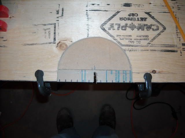 After cutting out a tooth, I'd just readjust my piece of acrylic, clamp it back in place and cut out another tooth. 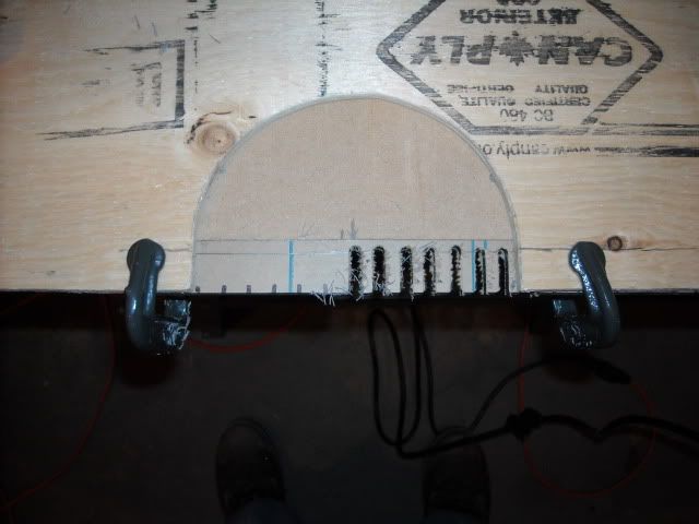 All the teeth cut out and my acrylic is still in one piece. Amazing! 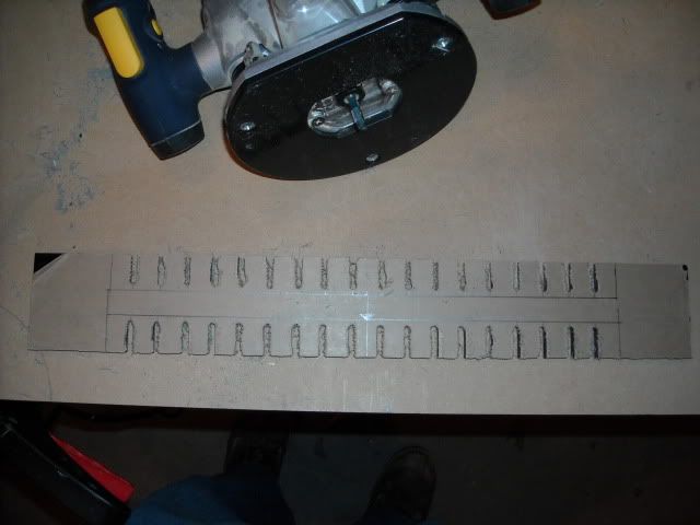 And all trimmed to size and dry fit 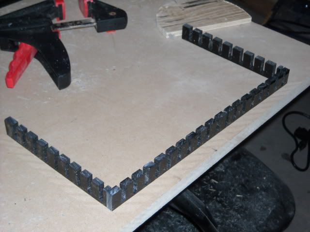 Siliconed onto the top of my overflow. Here you can also see the 2 outlets from my return pump. Each of these will be getting a 3/4" pacific coast flow accelerator which is basically a smaller version of an eductor. 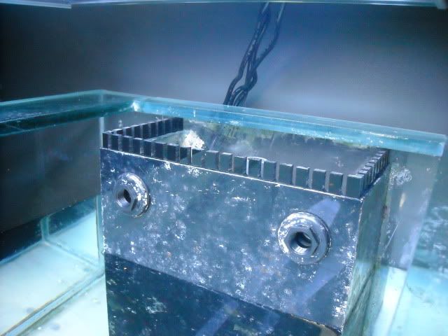 Well that about ends the DIY portion of my build until I get around to bracing my drain plumbing (since it is ridiculously heavy) and manifold into my stand as well as installing the doors on the stand and finishing the exterior.
__________________
Do or do not....there is no try.
|
|
#5
05-07-2010, 06:37 AM
|
|||||
|
|||||
|
Great looking build..
That first picture is a bit.. ouch ... but this tank looks to be shaping up to be a good place to regrow all you lost and then some, so I guess just keep looking forward..
__________________
-- Tony My next hobby will be flooding my basement while repeatedly banging my head against a brick wall and tearing up $100 bills. Whee!
|
|
#6
05-07-2010, 06:37 AM
|
|||||
|
|||||
|
And what do we have here!
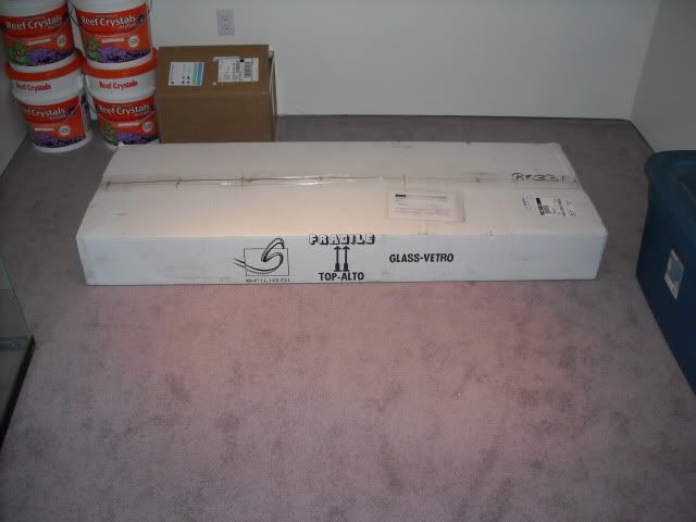 And after the quick install 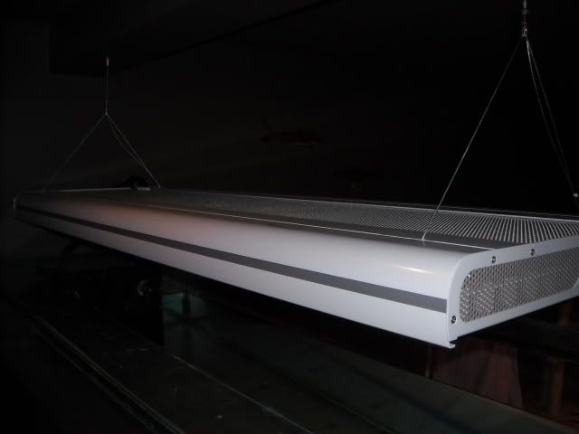 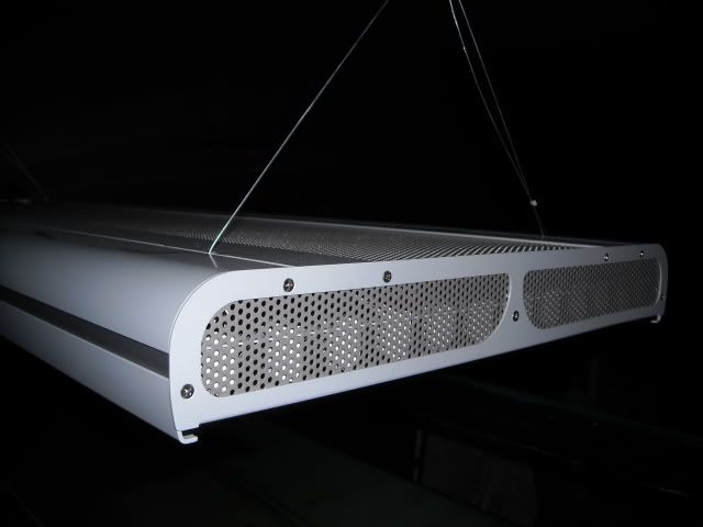 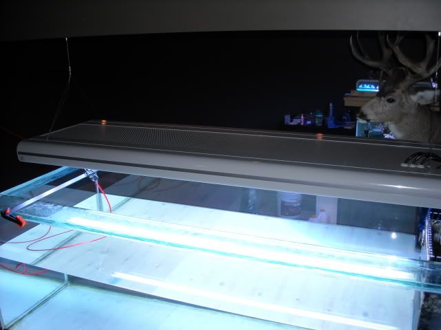 And here is one of the sweet moonlight I got Sfiligoi to install into the fixture. 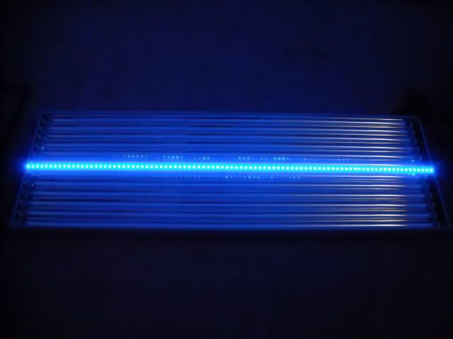 Lastly here is what the tank looks like after I got the black trim removed off the top. It took a full week of my RO/DI running 24/7 to get the waterline to where you see it now. I can't wait to see this months utilities bill! 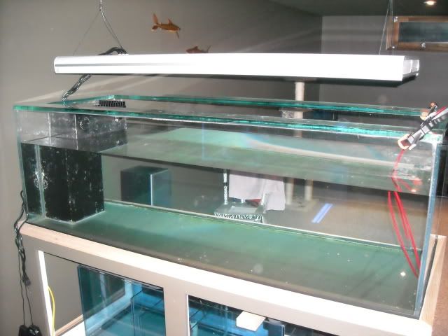
__________________
Do or do not....there is no try.
|
|
#7
05-07-2010, 08:34 AM
|
|||||
|
|||||
|
Yahoo looking great! Might I say...top shelf?
I loved your corals in the old 90 so I can't wait to see what you do here. Where are you buying 80w bulbs from? Nice touch with the added moonlights too.
|
|
#9
05-18-2010, 01:23 PM
|
|||||
|
|||||
|
Quote:
__________________
Do or do not....there is no try.
|
|
#10
01-21-2011, 09:56 PM
|
|||||
|
|||||
|
Well I have been slacking at keeping up with my build thread but work has been absolutely chaotic for nearly this entire year. I work out of town and have been away from home for 26+ days out of most months so needless to say, my tank hasn't been receiving much atttention.
With that said, I finally did some work to my tank here this week more out of necessity than anything. I purchased a Vertex Alpha 250 skimmer last year since my previous external skimmer had a tendency to flood my house if enough salt creep built up in the venturi. Since I'm usually gone for 7+ days at a time, this was obviously not the most ideal situation. I thought that an in sump skimmer would solve my problems as if anything were to go wrong, the skimmer would just overflow back into my sump and the worst that would happen would be a slight nutrient spike from the skimmate running back into the sump. Oh how I was wrong. In the event of a power outage and the level in the sump goes up past 10", or if a small piece of algae gets sucked into the skimmer pump's needle wheel, my skimmer starts to overflow in about 5 seconds. Once the collection cup is full of water, the collection cup basically gets air locked and a geysier of air and water erupts out of the 4 vent holes in the lid of the collection cup. This water then sprays all over the inside of my stand, coats all of my electronics in a saltwater mist and I end up with a ton of salt creep not to mention a nice puddle of saltwater in the base of my stand. So after spending $75 on a couple of float switches and a regulator module, I should never see my skimmer flood again. First off, I started with a narrow strip of black acrylic  After a generous application of heat from a butane torch and some careful bending I ended up with this 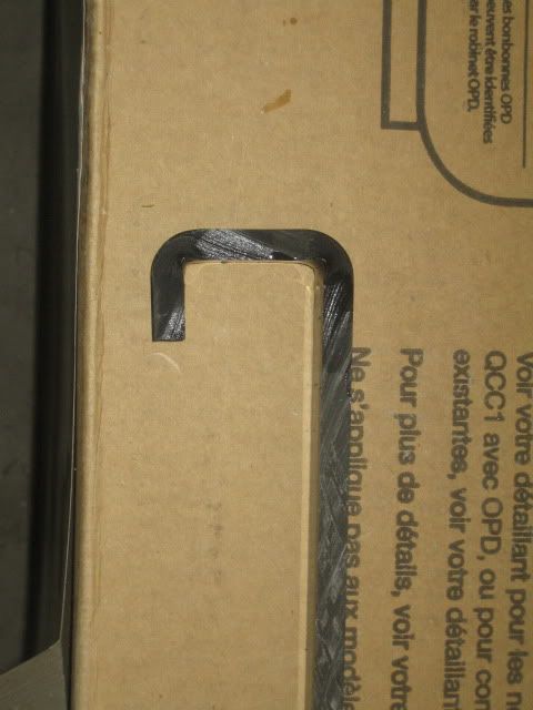 I then trimmed off the excess acrylic and drilled holes in both ends. One to accomdate the 1/4" NPT threads on the float switch. The other to accomdate the 1/4" standard threads on a nylon screw 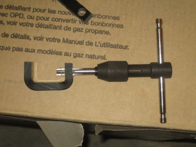 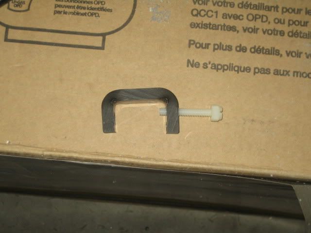 Here is a pic of the unit fully assembled with the float switch installed 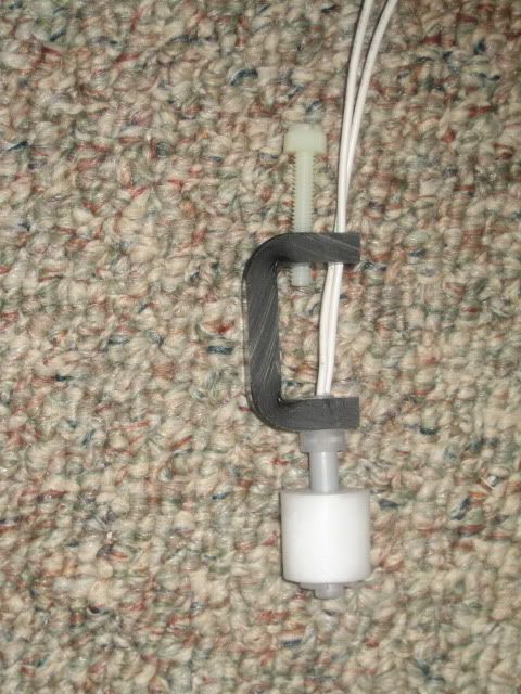 All I had to do then was push the float switch wires through one of the vent holes in the lid of my collection cup and then thread the nylon screw through the same hole to secure the float in place 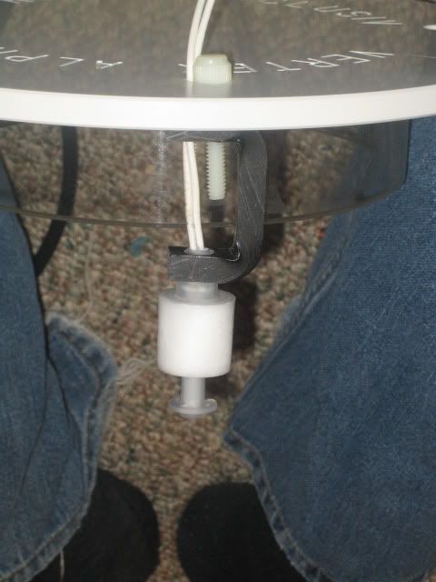 After installing the unit into my skimmer, I ended up changing the design to make the acrylic bracket shorter as well as shaped like an "S" instead of a "U". This was because the new shape allowed me to position the float so that it wasn't touching the outside or inner wall of the collection cup whereas with the "U" shaped bracket, I could not adjust it enough to clear both walls. I also installed male and female moisture proof connectors so that I can easily remove my collection cup for cleaning. 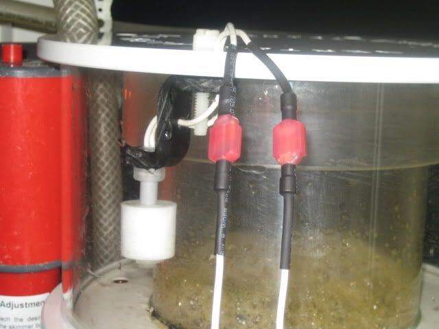 Here is an overview of the whole setup. Basically, so long as float #1 in the collection cup and float #2 in the sump are both suspended out of the water, the skimmer pump will be energized. If either switch floats up, the power will be immediately cut to the skimmer pump and will not be engergized until the float switch drops back down to its fully open position. This way, if my sump level comes up past 10" which it always does after a power outage, my skimmer pump will remain off until my sump level returns to normal thus preventing the collection cup from overflowing. If for some reason, my skimmer still decides to give me some unnecessary grief and start overflowing, the switch inside the collection cup will kill power to the skimmer as soon as it floats up to the closed position. This scenario is less ideal since the collection cup will have to be drained before the skimmer will resume operating however it will also prevent the dreaded saltwater geyseir that ends up flooding my tank stand. 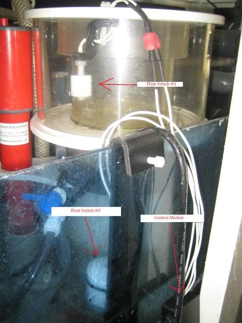
__________________
Do or do not....there is no try.
|


 Hybrid Mode
