
|
|
|
|
|
#1
 04-26-2013, 04:24 PM
|
|||||
|
|||||
|
Hi All,
I had bought a pair of Meanwell LPF series drivers for my project. However i soon found out these could not be dimmed using the conventional ways used to dim the popular ELN series drivers. After much head banging and some help from Fungus on the Arduino forum we found a solution that works great! You can use an Arduino to output the 0-5V PWM signal and the circuit turns it into 0-10V needed for the LPF series driver.  I hope this may help some of you and prevent the pure frustration i experienced!!!  VR
__________________
View my Aquarium & Reef Controller build here:  The Ultimate DIY Aquarium Controller of the 21st Century!!! LED's, PH, Salinity, Clock, LCD, ATO, Auto Water Changer, Variable Speed Cooling Fan Control and lots, lots more...... 
|
|
#3
04-26-2013, 08:08 PM
|
||||
|
||||
|
It's fairly straight forward. All you are doing in this set up is using the 0-5V PWM signal from the arduino to drive a 10V source - basically the same idea as an audio amplifier. You could easily solder this up on a proto board. Seems intimidating now but once you do it you'll see it's pretty easy. Probably take you 30-60 mins depending on your comfort level with circuitry and a soldering iron.
VR - What's with the NPN into the PNP? I'm not sure I get what that's for. Are you just trying to achieve higher gains to reduce the load on the arduino? If so, why not use a single darlington transistor instead?
|
|
#4
04-27-2013, 12:53 AM
|
|||||
|
|||||
|
No Idea Steve. My head was blown apart trying to figure this one and the guy on the arduino forum told me to try that circuit. I did not try driving the PNP directly from the arduino and my protoboard is now built, installed and running. Would be interesting to see without the 2n2222 in there.
__________________
View my Aquarium & Reef Controller build here: The Ultimate DIY Aquarium Controller of the 21st Century!!! LED's, PH, Salinity, Clock, LCD, ATO, Auto Water Changer, Variable Speed Cooling Fan Control and lots, lots more......
|
|
#5
04-27-2013, 06:52 AM
|
||||
|
||||
|
Ah, after looking at it more I see what he's doing. Ultra conservative design (in terms of current draw through the Arduino). You really could simplify it and just use the NPN. You'd have to drop the value of R3 to 5-10K butit'd work just the same.
Thanks for posting this. It'd be great to see people doing more DIY electronics. It's intimidating at first but easy once you get into it. Stuff like this really helps!
|
|
#6
04-27-2013, 12:42 PM
|
|||||
|
|||||
|
oops i forgot to add on a 1K pulldown resistor between the Meanwell + and 0V. This will prevent the driver from going to 100% brightness in the event the driver circuit stops working or has a power failure.
Steve, I tried using a NPN before and it would not drive the LPF series driver. Here is what i had tried before but with no luck: Controlling + lead:  So next i tried this circuit using the 10v supply to control the - lead: 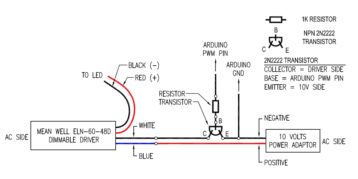 I then tried the following circuit as the 2 previous would not work. This i could get the drivers to dim but with the Arduino fading from 0-5v i could only get the circuit to output 3.5v-6.5v. 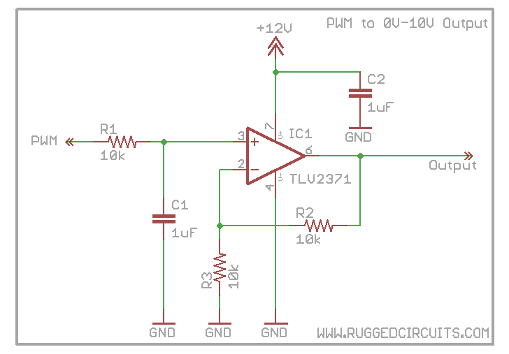 I hope the background helps.
__________________
View my Aquarium & Reef Controller build here: The Ultimate DIY Aquarium Controller of the 21st Century!!! LED's, PH, Salinity, Clock, LCD, ATO, Auto Water Changer, Variable Speed Cooling Fan Control and lots, lots more......
|


 Hybrid Mode
