
 |
|
||||||||
| Portal | PhotoPost Gallery | Register | Blogs | FAQ | Members List | Calendar | Search | Today's Posts | Mark Forums Read |
 |
|
|
Thread Tools | Display Modes |
|
#1
|
|||||
|
|||||
|
Well, after a brief discussion about this with Steve this morning, we figured it was time for a bit more DIY.
I will show first of all the mods done to the wp40, followed by the waveline pump(or in this case the attempt, but im pretty sure its all figured out already). I am using a P3 for control, with the base of a EVG card. With this, I have eliminated the need for the wp40 control and have complete control over the pumps with the profilux. Hoping to do the same with the waveline DC pumps. Please, keep the thread clean, I don't need it closed. Its here to be a help for everyone, I could also do this mod for the Apex as well. Ill post it here at a later date.
__________________
There's plenty of room for all God's creatures. Right next to the mashed potatoes. Last edited by The Codfather; 04-20-2013 at 06:38 PM. |
|
#2
|
|||||
|
|||||
|
For those that have been following the wp40 thread, this is not anything new.
Just a re-post. But there are a lot of similarities between the two, so thought I would include it. 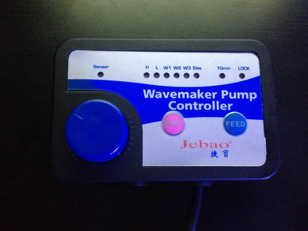 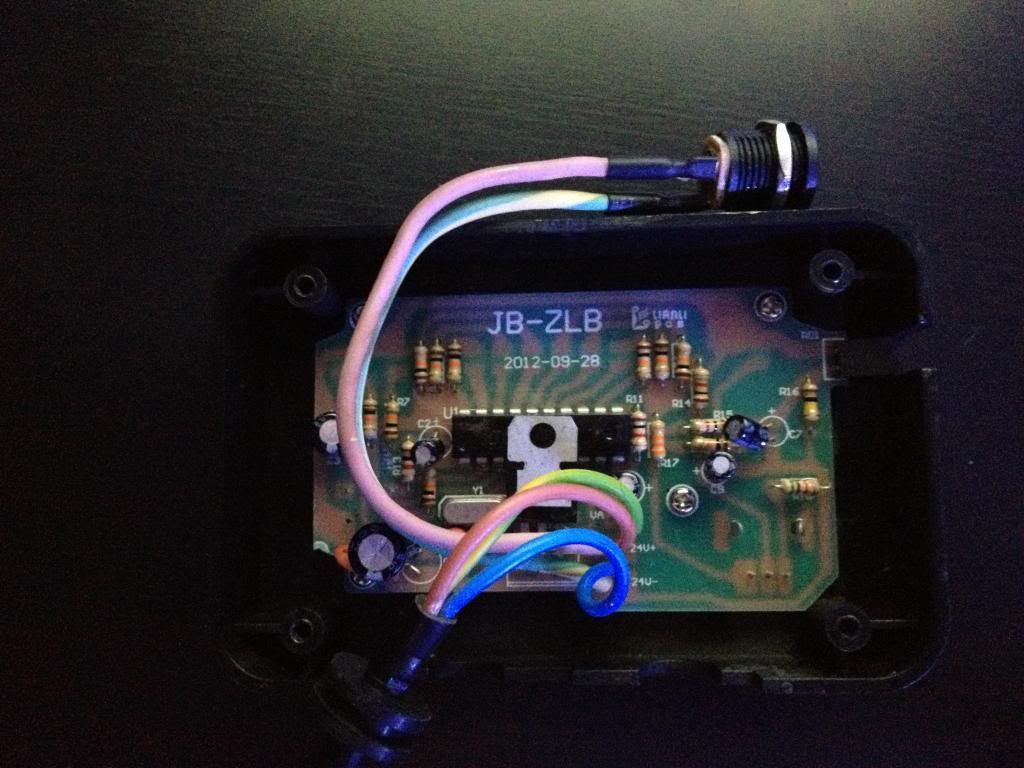 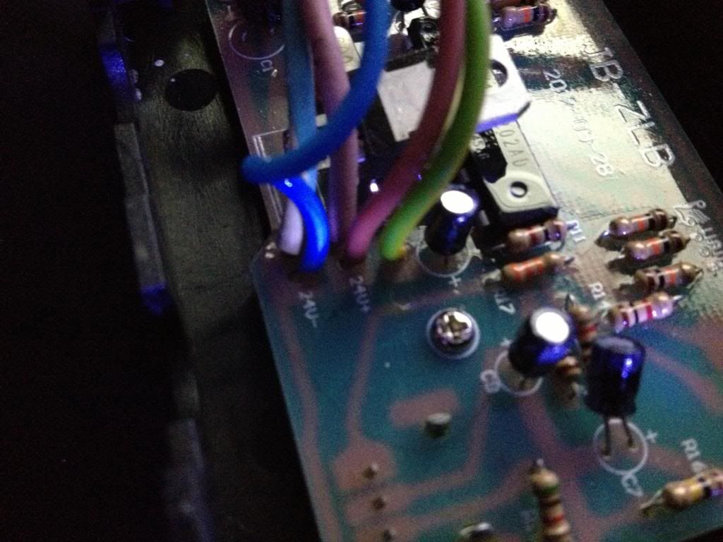
__________________
There's plenty of room for all God's creatures. Right next to the mashed potatoes. |
|
#3
|
|||||
|
|||||
|
__________________
There's plenty of room for all God's creatures. Right next to the mashed potatoes. |
|
#4
|
|||||
|
|||||
|
Just looking at it, Id say they are very close to comparison.
I have the WP40 completed and running, so a few things need to be figured out. More to come. Again, please lets keep the thread a clean one. Thanks for looking, Bob
__________________
There's plenty of room for all God's creatures. Right next to the mashed potatoes. |
|
#5
|
|||||
|
|||||
|
Consider this board cut in half.
The right hand side-110v The left hand side-low voltage. Right hand side.-Power comes in, splits to feed both AC/DC adapters. Upper left-to profilux Lower left-1-10v signals(or in the case of wp40 1-5v) 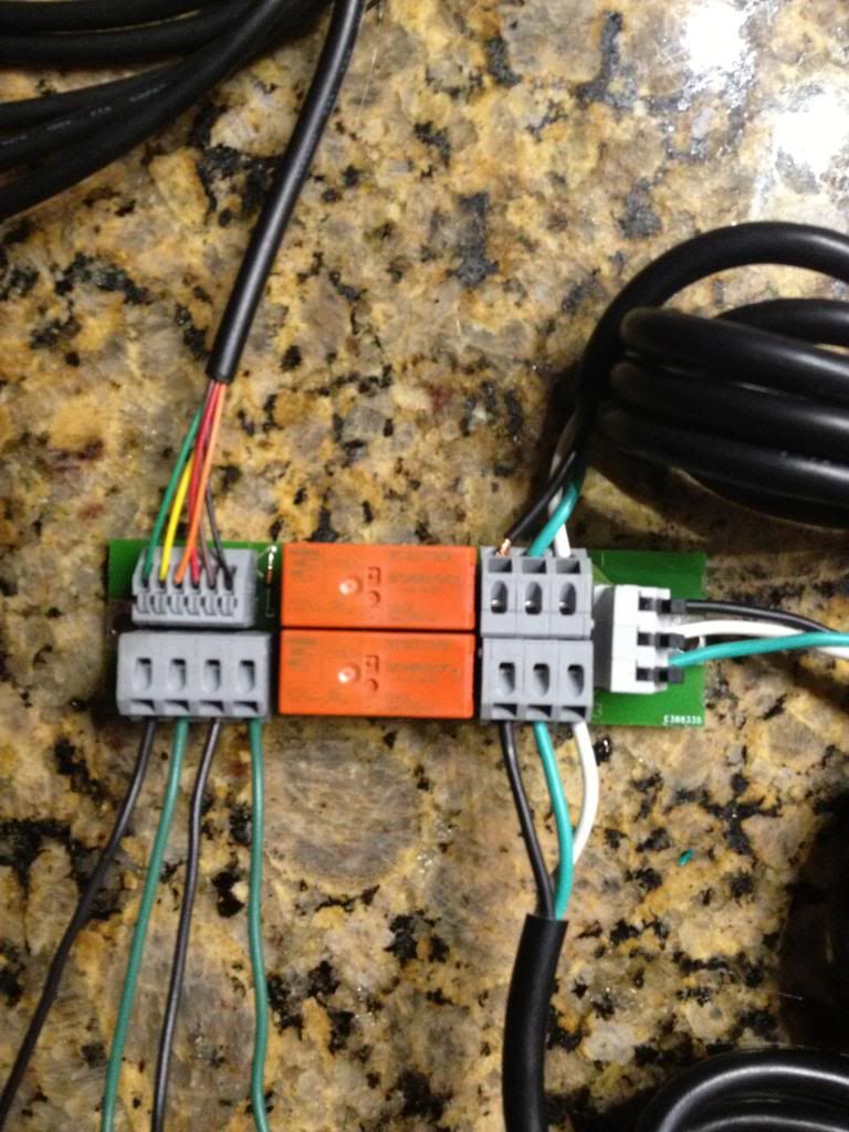
__________________
There's plenty of room for all God's creatures. Right next to the mashed potatoes. |
|
#6
|
|||||
|
|||||
|
__________________
There's plenty of room for all God's creatures. Right next to the mashed potatoes. |
|
#7
|
|||||
|
|||||
|
I just placed everything in a PVC box to keep it clean and neat.
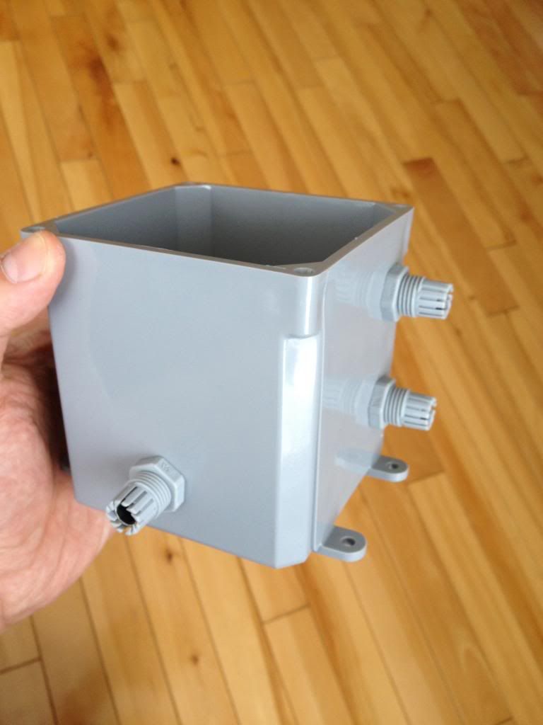 So what you see here is the completed box. The four connections that you see on the sides are: 1-110v power coming in. 2+3-110v power out-to AC/DC adapter 4-cable to profilux The top of the box has the two plugs from the AC/DC adapters, and the three prong that attaches to the pumps. The harness is just inside the casing. 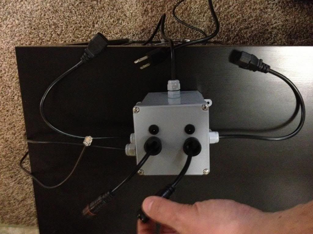
__________________
There's plenty of room for all God's creatures. Right next to the mashed potatoes. |
|
#8
|
|||||
|
|||||
|
Hooked up and mounted to under side of tank. I chose to run the two adapters externally because of the heat generated by them.
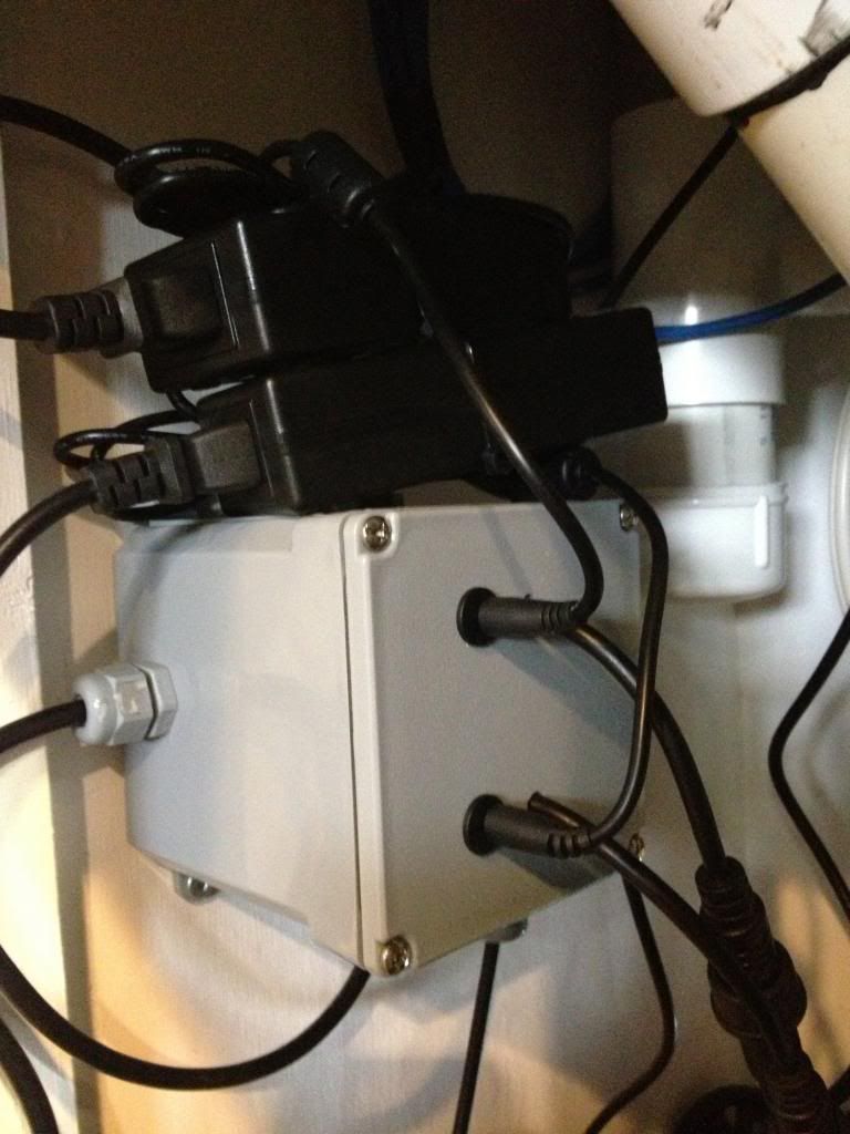
__________________
There's plenty of room for all God's creatures. Right next to the mashed potatoes. |
|
#9
|
|||||
|
|||||
|
Here is a few screen shots, if your familiar with the profilux, this was actually the easiest set up.
Set up 1-5 volt signal in 1-10v interface 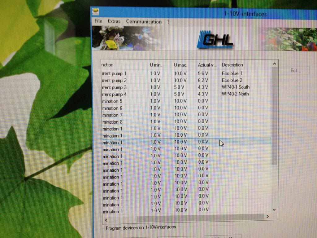 In current pumps, assign pump numbers and program. 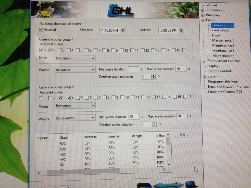 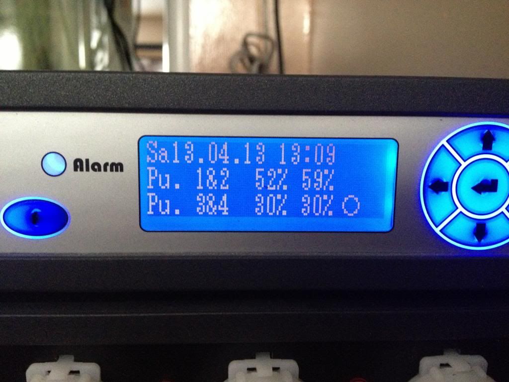
__________________
There's plenty of room for all God's creatures. Right next to the mashed potatoes. |
|
#10
|
|||||
|
|||||
|
Now that everyone is caught up, let's get started on the waveline.
With the controller open we can again identify the wires. 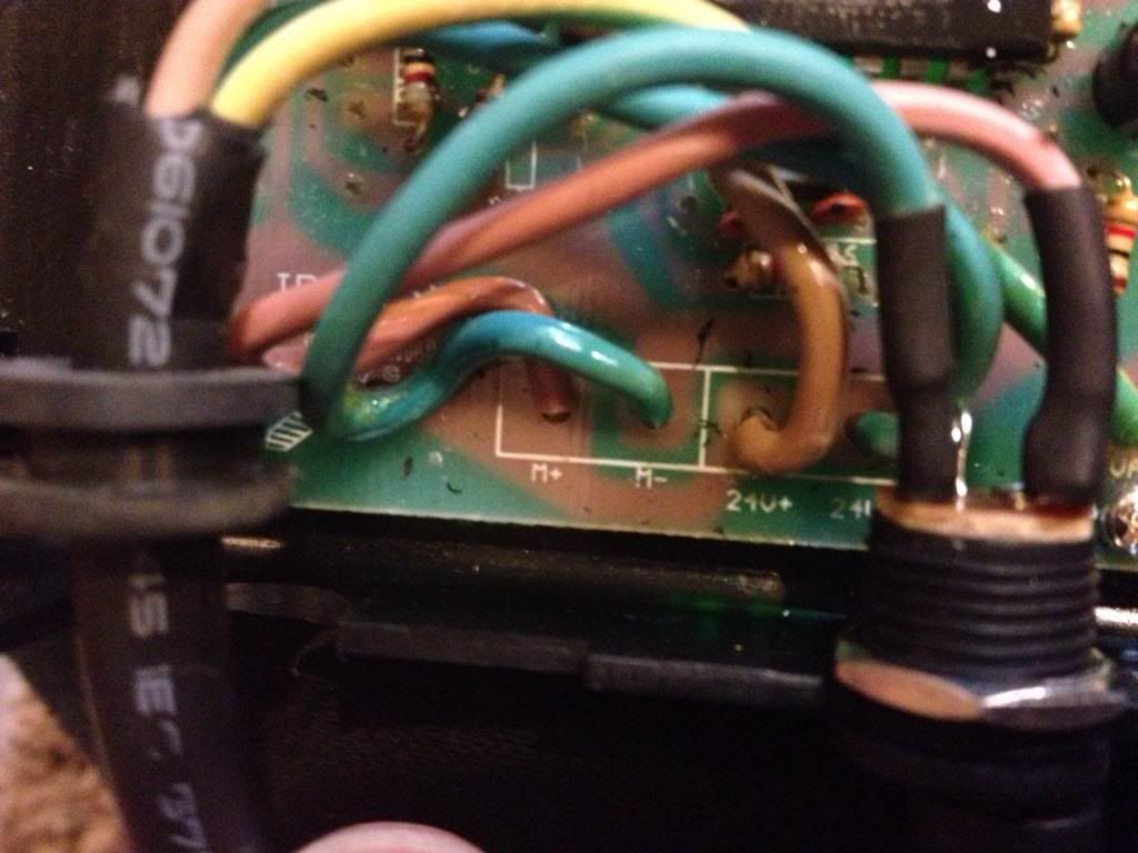 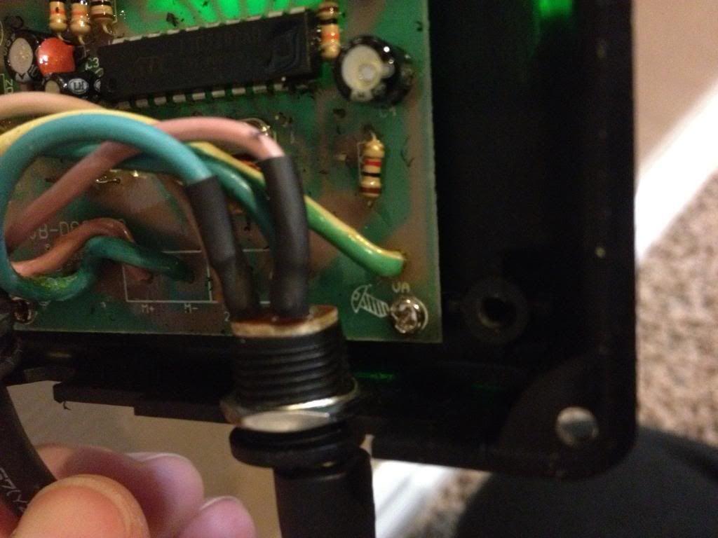 Again, two wires coming in off the AC/DC adapter, a positive and a negative. Labeled as M+ and M- on the board. Also three wires going to the pump, Labeled 24+, 24-, and VA.
__________________
There's plenty of room for all God's creatures. Right next to the mashed potatoes. |
 |
| Thread Tools | |
| Display Modes | |
|
|