
|
|
|
#31
 06-08-2013, 03:46 PM
|
||||
|
||||
|
So I think I have this cased then. I have three sections, each on a seperate non-GFI breaker: Display Tank; Frag Tank; Sump. I will only be powering lights and powerheads on the tank breakers, and the sump will take the rest. Smaller things like the fans, and lower outlets are technically GFI as there is one between the breaker ant the first outlet.
I can simply continue as I planned with 3 GFI outlets on each of the tank breakers. I think that this means that if the lights trip the GFI, the 2 other GFI outlets on the same line would still work. If this is true, I am OK. If this is false, I need to teach my electrician a thing or two! If the lights keep tripping, I think I can simply swap that outlet for a non-GFI and keep the other 2 as GFI. Let me know if this is the case. Here is what the setup would look like for both tanks: non-gfi breaker-----GFI outlet lights-----GFI outlet lights-----GFI outlet powerheads if that doesn't work: non-gfi breaker----- non GFI outlet lights-----non GFI outlet lights-----GFI outlet powerheads The setup for the sump would look like this: non-gfi breaker-----GFI outlet heaters------GFI outlet return pump------GFI outlet skimmer-------GFI outlet doser----GFI outlet light-----GFI outlet open-----GFI outlet open. Again, I was going with so many separate GFIs so if i had issues with any, all other things would work. If this is not the case, clearly the GFI outlets are redundant. I think this makes sense, and should work, but I could be wrong. I may need to feed each GFI individually from the main power ie: in parallel rather than in series. Let me know your thoughts, Magma. 
|
|
#32
06-08-2013, 03:57 PM
|
||||
|
||||
|
heres the thing I notice (now I would almost need to see it in person to actually see how its wired) but if you have for example the sump setup.
non-gfi breaker-----GFI outlet heaters------GFI outlet return pump------GFI outlet skimmer-------GFI outlet doser----GFI outlet light-----GFI outlet open-----GFI outlet open. Say your away for the day and all the GFI plugs are wired on the Load side starting from the heaters. If the light tripped the GFI and it actually went back and tripped the Heaters everything down the line would be off not saying it would happen but hey I have seen some weird things happen before (I tripped a dedicated lighting circuit in a panel downtown and took out the MAIN breaker for the building). So if that whole circuit is off for a day you have just lost, heat, skimmer, return, doser plus whatever else you want. But then again if the guy wired them correctly so they are all separate then if you trip the light plug the rest still keeps going. It all depends on how they are wired and its easy to screw up if your not paying attention. My suggestion would be anywhere you have a "GFI Outlet lights" change it to a standard plug no GFI. Ballasts trip GFI's randomly and if your lights are on a timer and your not home its asking for trouble. My whole tank is on 2 circuits in my house and I dont use one GFI plug or breaker. I have standard plugs with drip loops on all my cords. Thats just how I do it, everyone has there own ways.
__________________

|
|
#33
06-08-2013, 08:12 PM
|
|||||
|
|||||
|
As mentioned, having a lot of hardware on one GFI breaker is looking for trouble
I use a total of 13 GFCI duplexes and ran 2 15A circuits 'Almost' every individual piece of hardware I'm running has it's own duplex The only things that are doubled up are; My heaters, but there is another pair on a Ranco controller on it's own duplex, so no problem My UV and GFO are together My Skimmer and Carbon are together My Return pump and Tunze Osmolator are together (on purpose) My Chiller/UV pump and 'fuge' pump are together I run 4 T5HO ballasts and have never had an issue with the GFCIs The ballasts are connected through a PC4 power bar, so whether or not this solved any nuisance tripping or not I don't know I also installed Surge supressor duplexes to protect the solid state stuff, like my Controller, Vortechs and Battery B/U, and ATO I may have missed mention of it but are you going to use ground probes ? I have 5 DT, Sump, ATO tank, NSW mixing tank and QT Keep up the good work and enjoy your build
|
|
#34
06-08-2013, 09:07 PM
|
|||||
|
|||||
|
I have >600 watts of lighting and my return pump on one 20 amp GFCI breaker, and it has never tripped in the 2 years it's been installed. We first set it up with a GFCI receptacle and it would trip as soon as the halide ballasts tried to fire. My powerheads, doser, ATO, and skimmer are all on another 20 amp breaker with GFCI receptacles.
In my fish room I have 3 quad receptacles each with a GFCI receptacle that are all surface mounted by an electrician. There are also two standard in-wall dual receptacles in the room that were both plugged with those kid proof covers. I was short one plugin and decided to plug a Mag 3 pump into one of the in-wall receptacles to mix saltwater. It ran that way for several months without a hitch, and I forgot about it. I was away for the winter working in Alberta and I receive a panicked text message from the inlaws saying there is a firetruck at the house (ya thanks for the details!). It turns out the Mag 3 decided to seize and proceeded to overheat and the receptacle caught fire. Luckily there wasn't anything near the receptacle that would catch fire or the whole house could have burned down. Apparently the whole house was full of smoke, and I had to paint over the 18" black flame marks up the wall. When the receptacle caught fire it did eventually trip the (normal) breaker in the panel. If it was GFCI the receptacle probably wouldn't have caught fire to begin with. Moral of the story, Murphy's Law says it will be the ONE unprotected receptacle that will happen to have the ONE piece of equipment that will fail and cause your whole house to burn down. Now, all my fish related receptacles are protected. They have saved the bacon numerous times. I had a similar thing happen with a different mixing pump on a GFCI receptacle and it tripped the breaker at the very first spark. I was actually standing within 3' when that happened. Nearly pooped my pants. I also had a newly installed algae turf scrubber fall over in the sump overnight. It then shot water 4' up the wall directly at the plugs...of course. This tripped the GFCI and saved all the pumps in the sump that would have run dry otherwise, it also limited the amount of water on the floor. I slept like a baby through all this and groggy in bare feet before my morning coffee I walk in the room and wonder why the heck my feet feel wet. An aquarist wakes up real fast when the feet get wet for an unknown reason. Moral of those two stories, GFCIs are multi-purpose tools.  You have to figure out what you're comfortable with for yourself, and then you have to try to sleep at night for the first week it's running. Last edited by Myka; 06-08-2013 at 09:13 PM.
|
|
#35
06-09-2013, 02:22 AM
|
||||
|
||||
|
Quote:
Ground Probes have to be one of the worst things IMO. Your not fixing the problem at ALL! All you are doing is providing a path for current to flow. If you have that much voltage and current that you need a ground probe you have a problem and it needs to be fixed NOW. Voltage is not a problem, current is. BUT you can have voltage exist without current. Its how birds and squirrels can walk along the power lines and not end up as BBQ. Pretty good ready with some longer explanations can be found here: http://angel-strike.com/aquarium/GroundingProbes.html http://freshaquarium.about.com/od/pr.../grounding.htm (Tips and tricks) Lots more lengthy discussions on other forums and I find a lot of people have mixed feelings on this. But to me I find putting on a band-aid over a big problem on works for so long before it can be come a massive problem. Isolate the problem and replace the equipment.
__________________
|
|
#36
06-09-2013, 03:16 AM
|
|||||
|
|||||
|
Quote:
You're the electrician here But it's my understanding that using a GFCI 'without' a ground probe causes it to react slower, and a GFCI 'with' a probe protects life, as far as millisecond response time goes where heart issues are concerned Please explain how a ground probe 'can't' help trip a circuit faster than without one ....
|
|
#37
06-09-2013, 03:41 AM
|
||||
|
||||
|
Quote:
GFI's are set to trip with 5mA difference between the lines. You might feel a slight poke but its not going to drop you to the floor before it trips. I cant see it changing the reaction time to a point it would be noticed. IMO I think the ground probe can be ok if used correctly and you fix problems that arise. That being said, 9/10 times it makes us lazy in actually looking for the problem. So a $10 ground probe and 5 min to install problem "gone" or spend 20-30min tracing out which device is causing the leak and replacing something at a cost of 50? 100? 200? or more...your going to take the 10$ option every time and not truly fix the problem. I wont ever use a ground probe I would rather check my devices, use drip loops and isolate myself through the use of a mat or dry towel. Be safe and smart. Just take the time to check each device and replace it its going to save a lot more in the long run.
__________________
|
|
#38
06-20-2013, 08:15 PM
|
||||
|
||||
|
So, to catch some things up:
-No, I don't plan on using grounding probes. My mind is open to this idea and I may come around in the long run. -I worked out something to allow every plug to be GFI. Each separate breaker at each location will have a set of 3 plugs wired like this: Breaker A-----------GFI 1 I I I I I I-----------GFI 2 I I I-----------GFI 3 Definitely not three wires directly from the breaker as outlined, but wire through the wall to the triple box, then split to three. _____________ Onto bigger and better things: I called in the reinforcements to finish off the plumbing and HVAC. HVAC had to be done by a pro as per The City and plumbing was going to be a pain because of the 1.5" vent line for the sump. HVAC was simple. Core some holes:  IMG_2801 by gschaus, on Flickr Hook up the fans, flex and insulation. Tie into existing cold air return and insulate it as well. Exhaust: 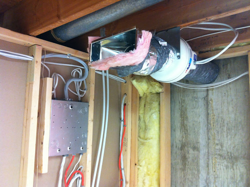 IMG_2811 by gschaus, on Flickr Return: 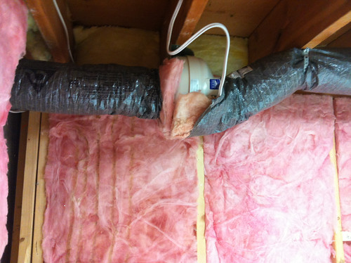 IMG_2812 by gschaus, on Flickr 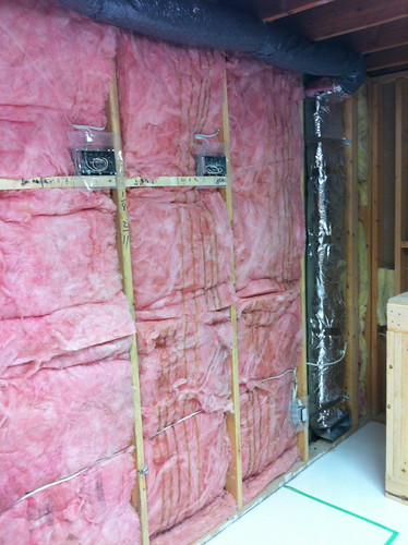 IMG_2813 by gschaus, on Flickr The only part remaining are two snorkels for the intake and exhaust vents on the outside of the house. These will get done tomorrow, at the same time as I get my main panel swapped out to gain extra room for the sub panel that I put in for this room. The tough part was still the plumbing. Hooking up the sump was straightforward enough, and getting the vent line out of the room was easy too. 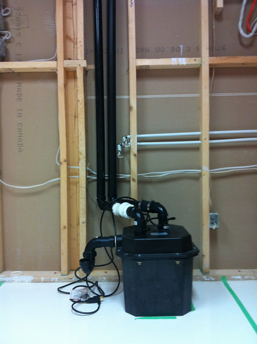 IMG_2810 by gschaus, on Flickr The tough part was tying in the vent line to the existing vent from a downstairs bathroom. Since we had to run the vent line from the sump, up the wall, into the furnace room, we were already at the same height as the existing vent line, but were still 6 feet and 4 joists away. This meant that we had to come down three inches or so, span the joists and go up again to connect to the vent. This would have left a trap for water and would have been against code. As there are no other vents in the area, and the house is finished, the contractor suggested a 1.5" cheater vent just before we drop below the joists. This is a bit of a grey area, but he says that inspectors sign off on this stuff all of the time for island sinks, etc. where there are no options for a vent. We will know if this is kosher on Monday, following the inspection. Hopefully all goes well, and it will be time to vapor barrier, drywall, mud/tape, paint and build the frag stand/counter. I have my 19mm Starfire on order and can't wait to get started on the fun stuff!
|
|
#39
06-28-2013, 04:21 AM
|
||||
|
||||
|
First things first: All the best to everyone affected by the flooding in Southern Alberta!
And speaking of the floods in Alberta, my inspections have been re-prioritized (rightfully so), as all of the inspectors are working on assessing homes for re-entry, etc. I don't have any idea when I will see an inspector, and the only reason I would hope for one soon, is to hope that the clean-up is quicker than anticipated. In the mean-time, I have my concerns as to whether the work done will pass inspection at all. Here are pics of the "1.5 inch cheater vent": 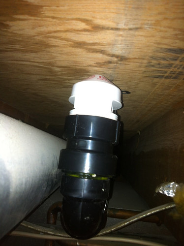 IMG_2862 by gschaus, on Flickr And the snorkels for the intake and exhaust respectively: 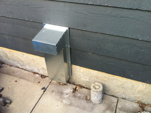 IMG_2857 by gschaus, on Flickr  IMG_2856 by gschaus, on Flickr I have concerns that the cheater vent will not be to code. And I have the same concern with the exhaust snorkel. It is my understanding that any vents need to be a minimum of 3' from any electrical junctions or windows. I would appreciate any information from anyone with an understanding of plumbing and HVAC codes. On the upside, my new main electrical panel was installed and it looks to be done correctly, and at a pretty respectable price. Here is a pic: 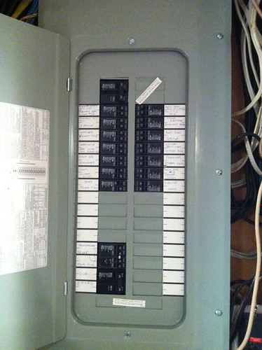 IMG_2831 by gschaus, on Flickr I am now going to frame in a bulkhead around the ventilation and wait for the inspectors. In the meantime, I'll have time to help out with the recovery.
|
|
#40
06-28-2013, 04:31 AM
|
|||||
|
|||||
|
Its been a couple years since I worked in HVAC in Alberta, but I believe you're correct. 1 meter from any exhaust vent to a building opening.
I'm not sure, but I thought they no longer allowed cheaters in the plumbing though.
|
 |
| Tags |
| diy, newbie, tank build |
|
|


 Linear Mode

