I sat down tonight and re-worked the sump drawing a little and actually drew it to scale.
I want the Deltec SC 2060 skimmer for this tank, which is 23.62 inches high (they say that includes an extra half inch for clearance), so if that happens, I can do this:
Make the sump 55" long X 29" wide X 24" tall. Taking in to account the 2 inch steel beams supporting the stand, that still gives me about a foot of floor space left over in the cabinet.
6" of that will be separated by a full height baffle and turned in to 4 dosing chambers which should be able to hold about 4 gallons of fluid each. They'll be separated from the sump by a half inch baffle. This will make the sump area 48.5"LX29"WX24"H. By making the sump 24" high, I can up the height of the water level in the sump from 12" like I had originally planned to 17", that will still give me 7" of space between the top of the water level and the rim of the sump, which is more than enough to cope with the extra water volume in a power failure.
By keeping the water level at 17 inches while the power is running, the sump will hold 103.5 gallons of water during normal operation, with a total capacity for 146 gallons when the power is off. I will need to put the skimmer on an 8 inch stand, but that will still give me almost 8 and a half inches of head room between the top of the skimmer cup and the bottom of the aquarium.
If I divide the sump perfectly in two, each half will hold about 50 gallons of water when the aquarium is running, which gets me almost exactly where I want for my water change system, as I want to be able to do at least a 50 gallon water change at once if I so desire.
So, assuming there's a half inch baffle between the two halves, that gives me 24X 29 inches on either side. I've given myself a 6x9.5 inch compartment for the drains from the tank. Hopefully that's big enough for two output pipes with enough room left over for me to change filter socks. I then left a 4 inch space for bubble trap baffles. I'm not sure if that's enough room for a bubble trap, I'll be getting Kevin's input on that. Then there is the skimmer chamber, it's just enough to get the skimmer in with a bit of clearance on either side. If this is too tight, I can cheat the centre baffle a couple of inches to the right and make the reactor/water change chamber a little smaller, or cheat the baffle that separates the skimmer chamber/input chamber out in to the refugium section, or both.
I added a baffle that cuts in to the middle of the reactor/water change section to encourage water to flow more in a U shape, as I don't want there to be any dead spaces in the corners. I'm not sure if it's necessary, or if it will make it hard to put in reactors so it might not be necessary. I also am not sure if this sump will allow micro-bubbles in to the display, so I added a possible space for another bubble catcher baffle set after the skimmer. It might not be practical to put one there, but if not there, I don't know where else!
Since I'll keep the water level at 17 inches high when it's running, I made the baffle between the input/skimmer chambers and the refugium be full height, except for a stretch right before the centre dividing baffle. There the baffle height between the skimmer chamber and the refugium drops to 18 inches (or maybe even 17.5) so that when the first gate valve is closed, the water in the chamber only has to go up by one (or half) an inch before it pours over in to the refugium, diverting flow away from the reacto/water change chamber. With such a small rise in water level, the skimmer will hopefully not go nuts when I divert the water directly to the refugium, and the water level in the refugium won't fall very much before more water stars pouring in to it. Once everything has reached equilibrium again, I will close the second gate valve, completely isolating the reactor/water change chamber from the system.
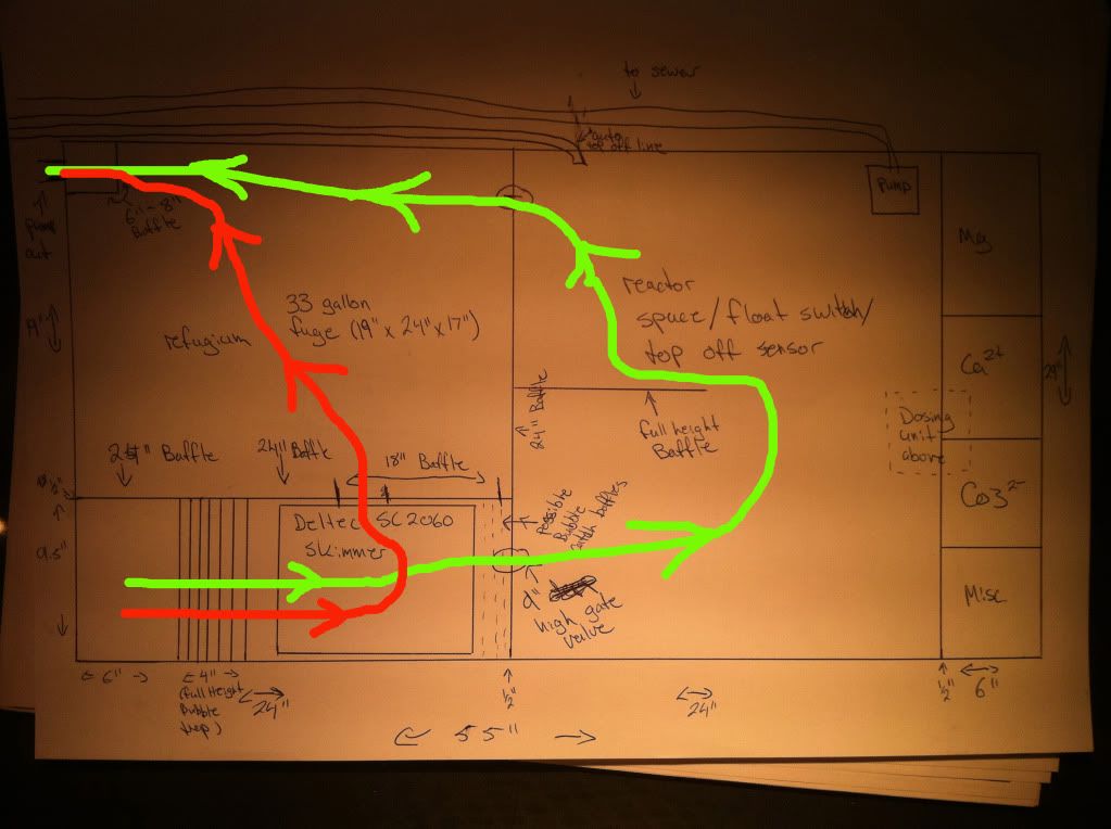
Green line is water flow when the gate valves are open, the red line is when the gate valves are closed. I also flipped it so that the external pump is on the side of the cabinet with the drain (where the RO unit will be), and the top off reservoirs will be right up against the side with the power supply. It will mean that the auto-top off line and the drain line will need to traverse the whole length of the sump, but since I'm only leaving 12 inches of space it lets me keep that 12 inches all on one side (the side with the R/O unit and external pump). It also means that the R/O unit won't have to be suspended above the dosing chambers, as I think that would make it hard to re-fill them.
I'm very open to suggestions, comments, or improvements. The sump will need to be ordered soon as it needs to go in before the stand, and they need the stand in place shortly after they start drywalling.